
Nuclear magnetic resonance analyzer and nuclear magnetic resonance measuring method

A technology of nuclear magnetic resonance and measurement method, which is applied in the direction of analysis using nuclear magnetic resonance, and can solve the problem of not being able to measure the relaxation characteristics and diffusion characteristics of the measured sample at the same time.

Active Publication Date: 2012-06-27
CHINA UNIV OF PETROLEUM (BEIJING)
View PDF2 Cites 58 Cited by
  • Summary
  • Abstract
  • Description
  • Claims
  • Application Information

AI Technical Summary

Problems solved by technology

[0004] The antenna of the existing nuclear magnetic resonance analyzer is usually made of a solenoid, and the magnetic field generated by the magnet is usually non-uniform, and there will be a gradual change between regions. The antenna is placed in the most uniform part of the magnetic field generated by the magnet, and then, using The antenna transmits radio frequency pulses and receives the echo signals of nuclear magnetic resonance. However, placing the antenna in a uniform static magnetic field can only measure the NMR relaxation characteristics of the tested sample, and the measurement of the diffusion characteristics of the tested sample needs to be performed in a gradient Therefore, in addition to the pulse gradient, the NMR analyzer relying on a simple coil cannot simultaneously measure the relaxation characteristics and diffusion characteristics of the tested sample, and the diffusion characteristic is also an important parameter reflecting the fluid type in the tested sample

Method used

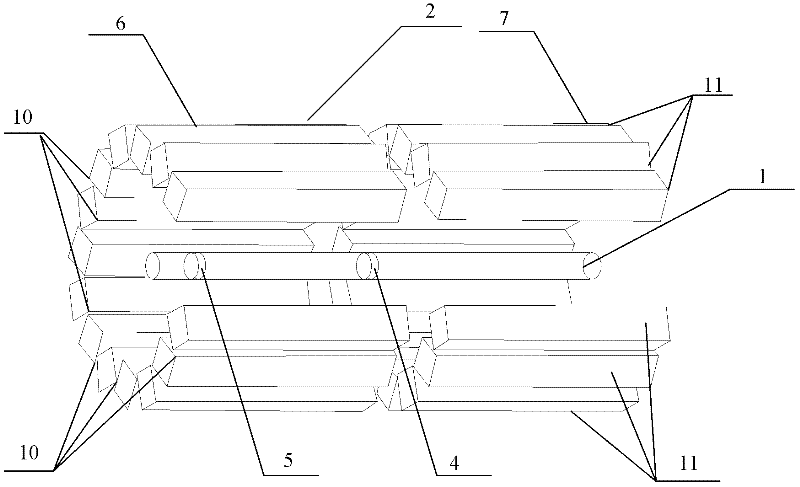
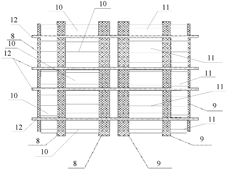

Image

  • Nuclear magnetic resonance analyzer and nuclear magnetic resonance measuring method
  • Nuclear magnetic resonance analyzer and nuclear magnetic resonance measuring method
  • Nuclear magnetic resonance analyzer and nuclear magnetic resonance measuring method

Examples


Embodiment Construction

[0043] An embodiment of the present invention provides a nuclear magnetic resonance analyzer, which includes a radio frequency circuit, a magnet, a glass tube, a first coil and a second coil.

[0044] The glass tube is used to place the sample to be tested, and the glass tube is fixed relative to the magnet and placed in the magnetic field generated by the magnet.

[0045] The first coil and the second coil are respectively wound on the outer surface of the glass tube and connected to the radio frequency circuit, and the first coil is placed at the uniform magnetic field generated by the magnet, and the second coil is placed at the gradient magnetic field generated by the magnet.

[0046] The magnet in the nuclear magnetic resonance analyzer is used to generate the static magnetic field required by nuclear magnetic resonance, and two forms of magnetic fields can be generated at different positions, one is a uniform magnetic field and the other is a gradient magnetic field. The...


PUM


Abstract

The invention discloses a nuclear magnetic resonance analyzer and a nuclear magnetic resonance measuring method. The analyzer comprises a radio frequency circuit, a magnet, a glass tube, a first coil and a second coil, wherein a sample to be measured is placed in the glass tube; the glass tube is fixedly arranged at a position opposite to the magnet and is placed in a magnetic field produced by the magnet; the first coil and the second coil are wound on the outer surface of the glass tube respectively and are connected with the radio frequency circuit; the first coil is placed at a uniform magnetic field produced by the magnet; and the second coil is placed at a gradient magnetic field produced by the magnet. Through the analyzer, distribution data of transverse relaxation time and longitudinal relaxation time of substances in the sample to be measured can be obtained, and distribution data of diffusion coefficients of the substances in the sample can be obtained.

Description

technical field [0001] The invention relates to oil well detection technology, in particular to a nuclear magnetic resonance analyzer and a nuclear magnetic resonance measurement method. Background technique [0002] The nuclear magnetic resonance analyzer uses the principle of nuclear magnetic resonance to conduct nuclear magnetic resonance experiments on the tested samples, and realizes the detection of the internal structure and macroscopic properties of the samples by analyzing the experimental data. [0003] Existing nuclear magnetic resonance analyzers mainly include magnets, radio frequency circuits, antennas, and echo analysis devices. The magnet is used to generate the static magnetic field required by nuclear magnetic resonance, the radio frequency circuit is used to generate radio frequency pulses, and the radio frequency antenna is used to generate a radio frequency field interacting with the static magnetic field and receive the echo of nuclear magnetic resonanc...

Claims


Application Information

Patent Timeline
Patent Type & Authority Applications(China)
IPC IPC(8): G01N24/08
Inventor 肖立志刘化冰于慧俊郭葆鑫胡海涛李新邓峰安天琳
Owner CHINA UNIV OF PETROLEUM (BEIJING)
Learn More