Testing method and testing device
A test method and test equipment technology, applied in the test field, can solve problems such as data destruction and data error
- Summary
- Abstract
- Description
- Claims
- Application Information
AI Technical Summary
Problems solved by technology
Method used
Image

Examples
Embodiment 1
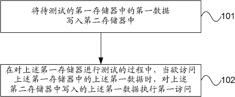
[0027] figure 1 It is a schematic flow chart of a test method provided by the embodiment of the present invention. Such as figure 1 Shown, the test method of the present embodiment comprises:
[0028] 101. Write first data in a first memory to be tested into a second memory.
[0029] 102. During the process of testing the first memory, when it is desired to access the first data in the first memory, perform a first access to the first data written in the second memory.
[0030] Both 101 and 102 involve access to memory. Accesses to memory can be read operations as well as write operations. The subject that accesses the memory may be the driver of the memory, or the test software, the operating system and the file system. Among them, the driver can directly access the memory. The operating system can access memory through drivers. When there is a file system, the file system can access the memory through the driver program under the control of the operating system. Test...
Embodiment 2
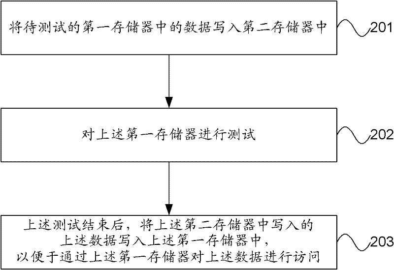
[0042] figure 2 It is a schematic flow chart of another testing method provided by the embodiment of the present invention. Such as figure 2 Shown, the test method of the present embodiment comprises:
[0043] 201. Write data in the first memory to be tested into the second memory.
[0044] 202. Test the foregoing first memory.
[0045] 203. After the test is completed, write the data written in the second memory into the first memory, so as to access the data through the first memory.
[0046] Both 201 and 203 involve access to memory. Access to memory can be a read operation or a write operation. The subject that accesses the memory may be the driver of the memory, or the test software, the operating system and the file system. Among them, the driver can directly access the memory. The operating system can access memory through drivers. When there is a file system, the file system can access the memory through the driver program under the control of the operating sys...
Embodiment 3
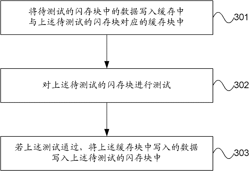
[0052] image 3 It is a schematic flowchart of another testing method provided by the embodiment of the present invention, and this embodiment is applicable to flash memory. Such as image 3 Shown, the testing method of the present embodiment can comprise:
[0053] 301. Write data in the flash memory block to be tested into a cache block corresponding to the flash memory block to be tested in the cache.
[0054] For example: the data in the flash memory block to be tested can be read first, and then the above data is written into the cache block corresponding to the flash memory block to be tested in the cache.
[0055] Wherein, the flash memory may be divided into several flash memory blocks of equal or different sizes.
[0056] Optionally, before 301, the correspondence between the at least one flash memory block and the cache block in the cache may be further established, so as to write the read data into the cache corresponding to the flash memory block to be tested in ...
PUM
 Abstract
Description
Claims
Application Information
 - R&D
- Intellectual Property
- Life Sciences
- Materials
- Tech Scout
- Unparalleled Data Quality
- Higher Quality Content
- 60% Fewer Hallucinations
Browse by: Latest US Patents, China's latest patents, Technical Efficacy Thesaurus, Application Domain, Technology Topic, Popular Technical Reports.
© 2025 PatSnap. All rights reserved.Legal|Privacy policy|Modern Slavery Act Transparency Statement|Sitemap|About US| Contact US: help@patsnap.com