Ophthalmologic apparatus and control method therefor
A kind of equipment, ophthalmology technology, applied in the direction of eye testing equipment, ophthalmoscope, medical science, etc., can solve the problems of difficult, time-consuming, and reduced accuracy of eyeball measurement
- Summary
- Abstract
- Description
- Claims
- Application Information
AI Technical Summary
Problems solved by technology
Method used
Image

Examples
no. 1 example
[0034] Hereinafter, a first embodiment of the present invention will be described.
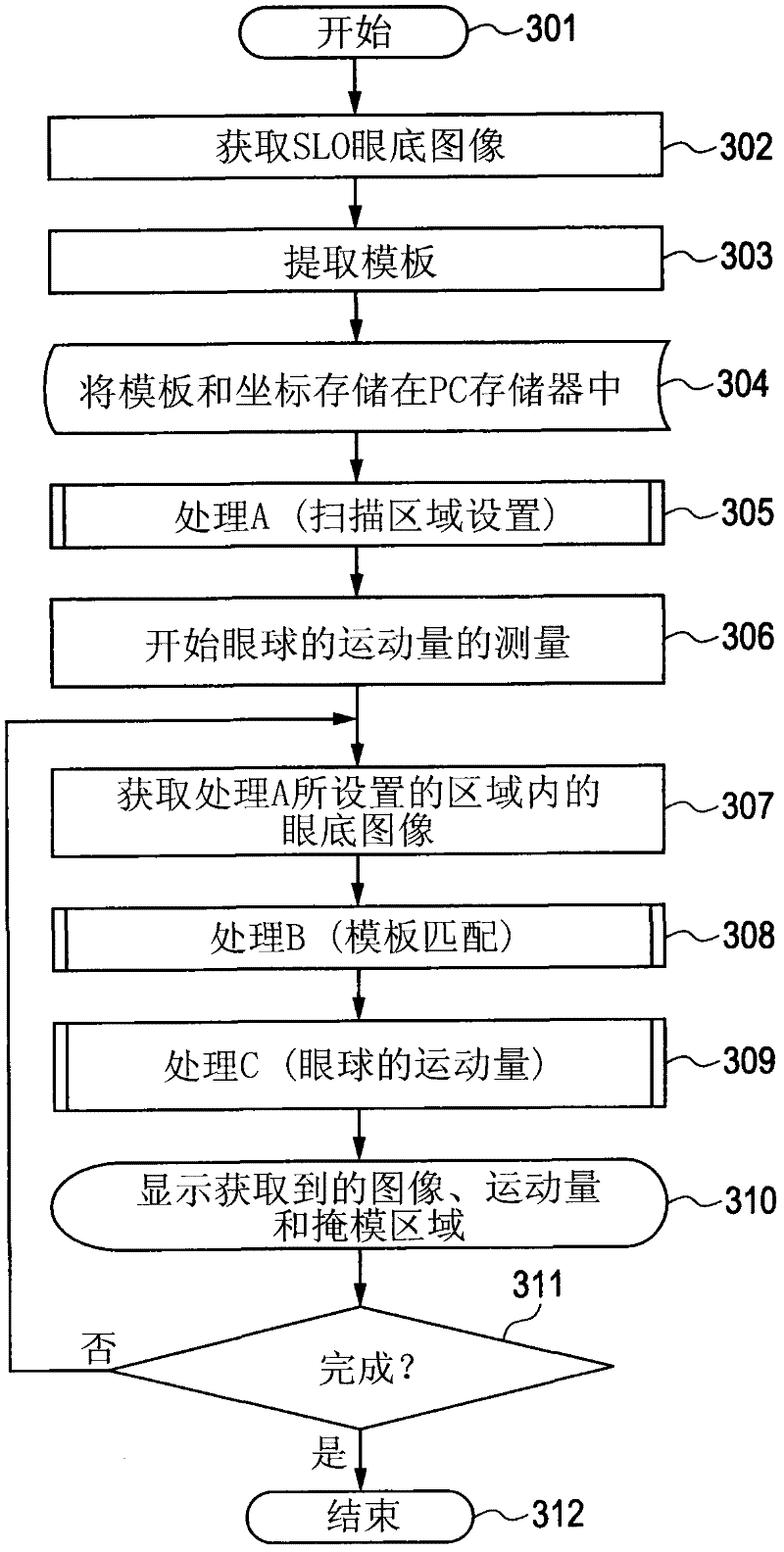
[0035] In the example described in this embodiment, after the fundus image is acquired and a plurality of feature points (also referred to as "multiple feature images") are extracted, the fundus area to be scanned is set, so that the eyeball can be measured at high speed. sports.
[0036] The overall structure of the device
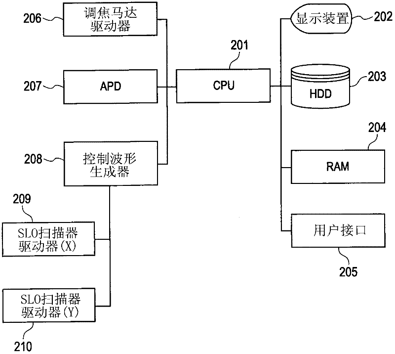
[0037] The fundus imaging apparatus of the present embodiment includes scanning laser ophthalmoscope (SLO) imaging means and control means.
[0038] SLO Camera Parts
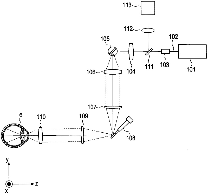
[0039] refer to figure 1 The optical structure of the SLO imaging unit will be described.
[0040] As the laser light source 101, a semiconductor laser or a superluminescent diode (SLD) light source can be suitably used. As for the wavelength to be used, in order to reduce glare of the subject and maintain resolution at the time of fundus observation, a near-infrared wavelength region in the range ...
no. 2 example
[0063] Hereinafter, a second embodiment of the present invention will be described.
[0064] In the example described in this embodiment, after the fundus image is acquired to extract the feature points, the area to be scanned is set, thereby enabling high-speed measurement of the movement of the eyeball. At the same time, by providing feedback to an optical coherence tomography (OCT) device, OCT images with high image quality (three-dimensional images with small positional shifts) are obtained.
[0065] The overall structure of the device
[0066]The fundus imaging device of this embodiment includes OCT imaging means, SLO imaging means, and control means. Each component will be described in detail below.
[0067] Optical structure of OCT imaging components
[0068] refer to Figure 11 The optical configuration of the OCT imaging unit of this embodiment will be described.
[0069] As the low-coherence light source 1101, a superluminescent diode (SLD) light source or a...
no. 3 example
[0096] A third embodiment of the present invention will be described below.
[0097] The third embodiment relates to a mode of a fundus imaging apparatus including: a setting unit for acquiring a fundus image, extracting a plurality of feature images, and setting a feature image containing a plurality of feature images in the imaging area. a partial area of at least one characteristic image; a partial image acquiring unit for acquiring an image of the set partial area by scanning the set partial area with measurement light; and a measuring unit for measuring movement of the fundus by template matching, Wherein, in the template matching, similarities between the multiple feature images and the image of the partial region are searched for and judged.
[0098] In the example described in this embodiment, after a plurality of feature points are extracted, an area to be scanned is set, thereby enabling high-speed measurement of the movement of the eyeball. At the same time, by p...
PUM
 Abstract
Description
Claims
Application Information
 - R&D
- Intellectual Property
- Life Sciences
- Materials
- Tech Scout
- Unparalleled Data Quality
- Higher Quality Content
- 60% Fewer Hallucinations
Browse by: Latest US Patents, China's latest patents, Technical Efficacy Thesaurus, Application Domain, Technology Topic, Popular Technical Reports.
© 2025 PatSnap. All rights reserved.Legal|Privacy policy|Modern Slavery Act Transparency Statement|Sitemap|About US| Contact US: help@patsnap.com