

Displacement detection apparatus
a technology of displacement detection and detection apparatus, which is applied in the direction of instruments, measurement devices, interferometers, etc., can solve the problems of limited use conditions, and achieve the effects of high precision, high speed and stable measuremen
- Summary
- Abstract
- Description
- Claims
- Application Information
AI Technical Summary
Benefits of technology
Problems solved by technology
Method used
Image

Examples
first embodiment
A Displacement Detection Apparatus Having Arranged Therein a Diffraction Grating That Cancels a Change of an Optical Path Length
1-1. Configuration
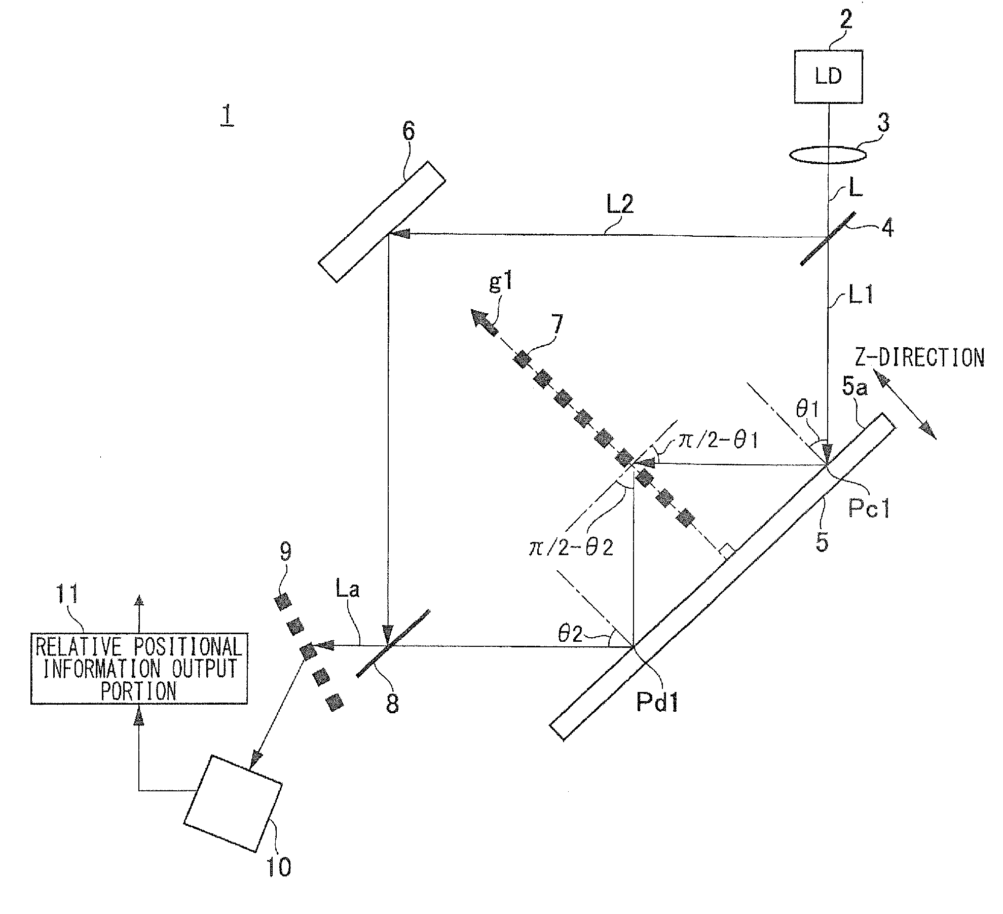
[0035]FIG. 1 is a schematic configuration diagram of a displacement detection apparatus according to a first embodiment of the present invention. A displacement detection apparatus 1 according to the embodiment detects a displacement in the height direction of a member to be measured 5, using a transmission-type first diffraction grating 7. Here, the height direction refers to a direction perpendicular to a surface to be measured 5a when the surface to be measured 5a of the member to be measured is assumed to be a plane, and is indicated as a z-direction in FIG. 1. As illustrated in FIG. 1, the displacement detection apparatus 1 includes a light source 2, a light flux dividing portion 4, a first diffraction grating 7, a reflection portion 6, a light receiving portion 10, a second diffraction grating 9, and a relative positional informatio...
second embodiment
2. Second Embodiment
A Displacement Detection Apparatus Having Arranged Therein a Diffraction Grating That Cancels a Change of an Optical Path Length and a Change of the Wavelength of a Light Source
[0116]FIG. 9 is a schematic configuration diagram of a displacement detection apparatus according to a second embodiment of the present invention. A displacement detection apparatuses 20 according to the embodiment differs from the displacement detection apparatus 1 according to the first embodiment in that the second light flux L2 is diffracted by the first diffraction grating 7 and that a third diffraction grating 21 is provided in the vicinity of the light source 2. In FIG. 9, the portions corresponding to those of FIG. 1 are given the same reference numerals to omit the duplicated description.
[0117]In the embodiment, a reflection portion 22 is arranged at a position facing the member to be measured 5 across the first diffraction grating 7. Moreover, the reflection portion 22 is prefera...
third embodiment
3. Third Embodiment
A Displacement Detection Apparatus Having Arranged Therein a Diffraction Grating That Cancels a Change of an Optical Path Length and a Change of the Wavelength of a Light Source
[0125]Next, a displacement detection apparatus according to the third embodiment of the present invention is described. FIG. 10 is a schematic configuration diagram of the displacement detection apparatus according to the embodiment. A displacement detection apparatus 30 according to the embodiment differs from the displacement detection apparatus 20 according to the second embodiment in that the first light flux L1 and second light flux L2 are caused to enter the first diffraction grating 7 twice and then enter the light receiving portion 10. In FIG. 10, the portions corresponding to those of FIG. 1 and FIG. 9 are given the same reference numerals to omit the duplicated description.
3-1. Configuration
[0126]As illustrated in FIG. 10, in the displacement detection apparatus 30 according to th...
PUM
 Abstract
Description
Claims
Application Information