Test-tube stand fixing device and method, and blood analysis device thereof

A fixing device, a technology for blood analysis, applied in chemical instruments and methods, analytical materials, biological testing, etc., can solve the problems of test tube rack pressing, unable to achieve linear contact pressing, affecting the operation of the push claw, and achieving reliable The effect of compressing the test tube rack

Active Publication Date: 2012-07-04
SHENZHEN MINDRAY BIO MEDICAL ELECTRONICS CO LTD
View PDF4 Cites 14 Cited by
  • Summary
  • Abstract
  • Description
  • Claims
  • Application Information

AI Technical Summary

Problems solved by technology

When the elastic device is used for a long time, the elastic force will become smaller, resulting in no fixation; in addition, the elastic device cannot completely press the test tube rack, otherwise it will affect the reliable operation of the test tube rack by the push claw
[0004] (2) There is a power device at the lower end of the test tube rack. When the test tube rack moves to the sampling position, the power device presses the test tube rack on the bottom plate in the vertical direction, because the working block of the device is just a simple flat plate. When the contact surface between the test tube rack and the bottom plate and the bottom plate are deformed, the two-point linear contact compression cannot be realized. In addition, when two test tube racks need to be pressed at the same time, if there is an error in the height dimension of the pressing position of the two test tube racks, only One test tube rack can be compressed, so there is a certain risk of failure in the application of this solution. At this time, the power shaft of the compression device will bear a certain radial force, which will also reduce the service life; and the function point of the device At the bottom of the test tube rack, and the impact point of the test tube rack is on the upper part of the test tube rack, and the impact force along the horizontal direction, so that the pressing force point of the device is far away from the impact force point of the jaws, and is also along the vertical direction , not in the direction of the impact force, so that under the same force, the actual compression effect will be significantly reduced

Method used


Image

  • Test-tube stand fixing device and method, and blood analysis device thereof
  • Test-tube stand fixing device and method, and blood analysis device thereof
  • Test-tube stand fixing device and method, and blood analysis device thereof

Examples


Embodiment approach

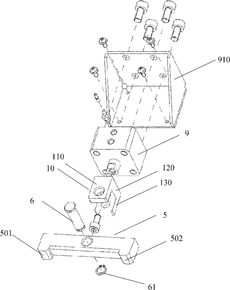
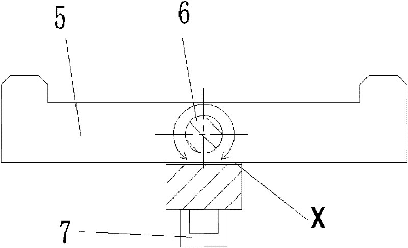
[0023] Such as figure 1 Shown is an embodiment of the test tube rack fixing device of the present invention, including a base plate (not shown in the figure), a support 10, and a briquetting block 5, and the base plate is the base of the entire test tube rack fixing device. The power unit is connected to the base plate. The power unit can be a cylinder as the power unit, a hydraulic cylinder as the power unit, or a motor as the power unit. In one embodiment, as figure 1 , with cylinder 9 as power unit, and cylinder block 910 in addition. The connection can be a fixed connection, such as riveting, welding, screw connection and other connection methods. The pressure block 5 is connected to the bracket 10, and the connection may be a fixed connection or a rotational connection. The output shaft 7 of the air cylinder drives the support 10 to move, and the support 10 drives the briquetting block 5 to move towards the test tube rack to press the test tube rack, thereby realizing...


PUM


Abstract

The invention discloses a test-tube stand fixing device, which comprises a baseboard, a power device, a support and a pressure block, wherein the power device is connected with the baseboard, an output shaft of the power device is connected with the support, the pressure block is connected with the support, the output shaft of the power device drives the pressure block to move towards the direction of the test-tube through the support, and the pressure block is pressed on the side wall of the test-tube when the output shaft stops moving. The output shaft of the power device is connected with the support, the support is driven by the output shaft to move, the pressure block is connected with the support, the support drives the pressure block to move, the output shaft of the power device drives the pressure block to move towards the direction of the test-tube stand through the support, thus the test-tube stand is pressed, an pressure point is close to the location of the test-tube stand, which bears an impact force, and the test-tube stand is more realizably pressed.

Description

technical field [0001] The invention relates to a blood analysis device, especially a test tube rack fixing device and method. Background technique [0002] The sampling process of some existing blood analysis devices equipped with automatic sampling is as follows: firstly, a push claw pushes the test tube rack so that it runs along a running channel to the sampling position and then stands still, and the push claw returns to the initial position. The push claw of the model will give a certain impact force to the test tube rack, and then the clamping mechanism will take the test tube out of the test tube rack, and then put it into the test tube rack after mixing and sampling. The running channel here It is composed of a front board, a rear board and a bottom board. The distance between the front board and the rear board can be adjusted according to the operation requirements. It is necessary to keep the test tube rack fixed during the retraction of the push claws, and the p...

Claims


Application Information

Patent Timeline
Patent Type & Authority Applications(China)
IPC IPC(8): B01L9/00G01N35/00G01N35/10G01N33/48
Inventor 朱景国
Owner SHENZHEN MINDRAY BIO MEDICAL ELECTRONICS CO LTD
Why Eureka
Try Eureka