Locking device for vehicle battery box

A locking device and battery box technology, applied in the direction of electric power devices, power devices, vehicle parts, etc., can solve the problems of complex form and structure, troublesome operation, etc.

Active Publication Date: 2012-07-04
亿源动力(北京)科技有限公司
View PDF4 Cites 23 Cited by
  • Summary
  • Abstract
  • Description
  • Claims
  • Application Information

AI Technical Summary

Problems solved by technology

Generally, the existing battery disassembly and locking requires an external power source such as an electronic control system to cooperate, and this form has a complex structure and troublesome operation. In order to make the battery safe, reliable and convenient to install on the electric vehicle or charging stand It is a technical problem that has not been resolved so far

Method used


Image

  • Locking device for vehicle battery box
  • Locking device for vehicle battery box
  • Locking device for vehicle battery box

Examples


Embodiment Construction

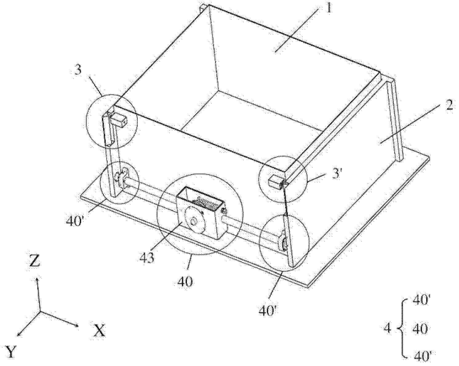
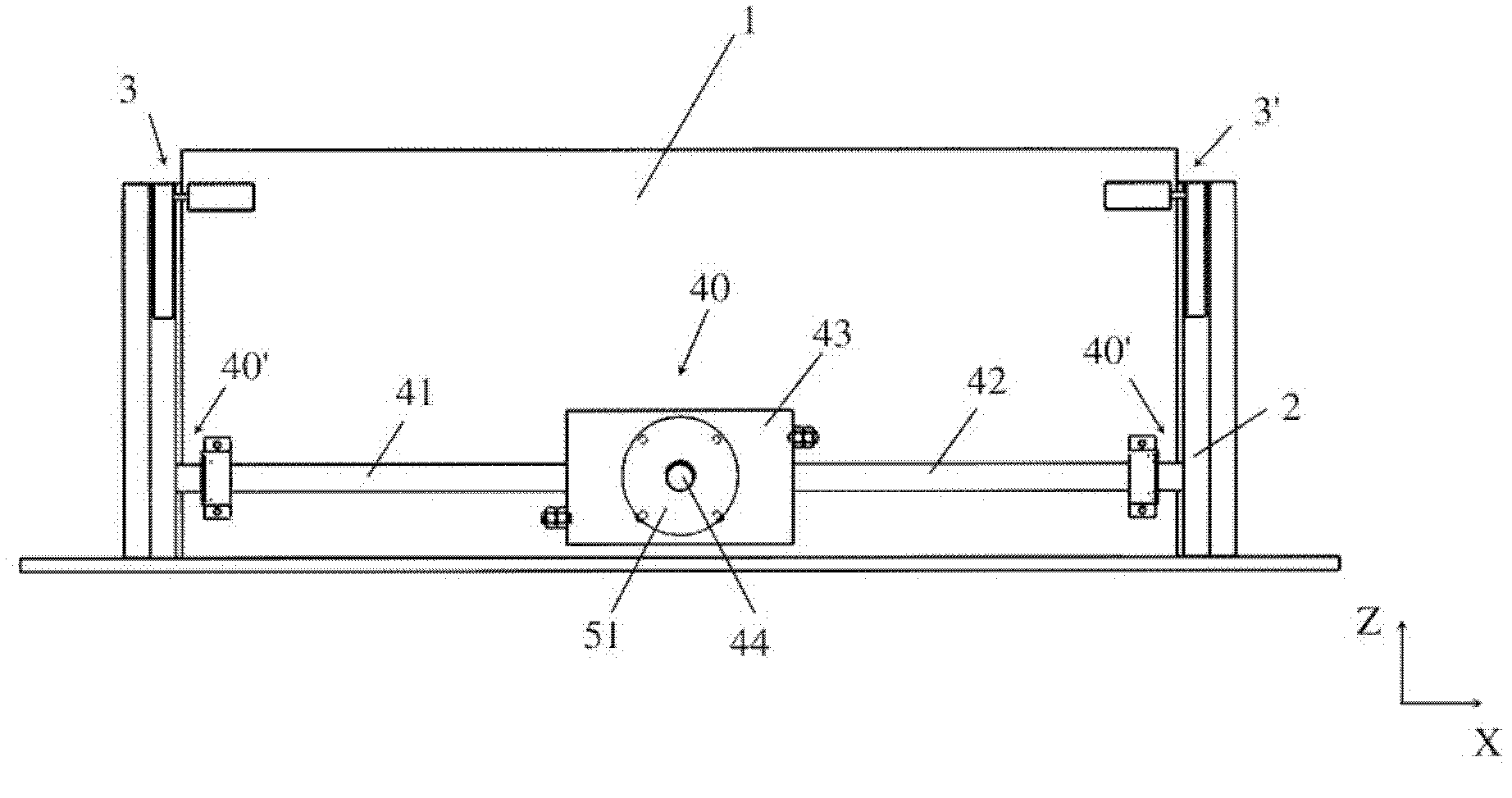
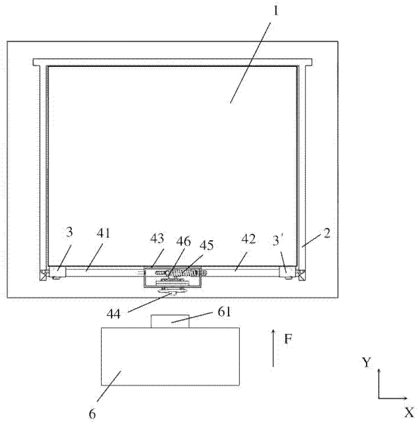
[0050] Please see figure 1 , the present invention discloses a locking device for a vehicle battery box, which is used to lock a battery box 1 containing batteries (not shown) on a battery rack 2, wherein the battery rack 2 can be used for storing the battery box 1 The battery charging stand for charging can also be a battery outer box for placing the battery box 1 on the electric vehicle, so they are collectively referred to as the battery stand 2 . The locking device includes: two mutually symmetrical positioning mechanisms 3, 3' for positioning the battery box 1 on the battery rack 2; an unlocking mechanism 4 set on the battery box 1 for locking and unlocking The battery box 1 is on the battery rack 2 ; and the loading and unloading mechanism 6 is arranged outside the battery box 1 for controlling the locking or unlocking action of the unlocking mechanism 4 and loading and unloading the battery box 1 .

[0051] The two mutually symmetrical positioning mechanisms 3, 3' (suc...


PUM


Abstract

The invention discloses a locking device for a vehicle battery box. The locking device is used for locking a battery box in which batteries are arranged to a battery rack; the locking device comprises two positioning mechanisms, an unlocking mechanism and an assembling and disassembling mechanism, wherein the two positioning mechanisms are mutually symmetrical and are used for positioning the battery box on the battery rack; the unlocking mechanism is arranged on the battery box and used for locking the battery box to the battery rack and unlocking; and the assembling and disassembling mechanism is used for controlling the locking or unlocking action of the unlocking mechanism and assembling and disassembling the battery box. By matching of the positioning mechanisms, the unlocking mechanism and the assembling and disassembling mechanism, the locking device is easy to operate and reliable and can finish positioning, locking, unlocking, assembling and disassembling operation in the absence of external tools. By combining a joint mechanism, the battery box is more convenient to assemble and disassemble.

Description

technical field [0001] The invention relates to a locking device for a vehicle battery box, in particular to a locking device for a battery box of an electric vehicle or a bus system without external sources. Background technique [0002] At present, electric vehicles are equipped with rechargeable batteries. When the rechargeable batteries are exhausted, they need to be replaced, which is what people often call charging and battery replacement. Transferring the battery to be recharged to the charging rack of the charging station is a set of tedious work, so it will face the problems of how to disassemble, assemble, and place the larger and heavier battery more conveniently. Generally, the existing battery disassembly and locking requires an external power source such as an electronic control system to cooperate, and this form has a complex structure and troublesome operation. It is a technical problem that has not been resolved so far. Contents of the invention [0003]...

Claims


Application Information

Patent Timeline
Patent Type & Authority Applications(China)
IPC IPC(8): B60K1/04
Inventor 刘渊文
Owner 亿源动力(北京)科技有限公司
Why Eureka
Try Eureka