Vibrating parts feeder

A technology for conveying devices and parts, which is applied in the field of vibrating parts conveying devices, and can solve problems such as difficulty in adjustment and increased vibration

Active Publication Date: 2012-07-04
NTN CORP
View PDF9 Cites 4 Cited by
  • Summary
  • Abstract
  • Description
  • Claims
  • Application Information

AI Technical Summary

Problems solved by technology

[0010] However, in such a compound vibrating disk feeding device, if the natural frequency F of the disk in the horizontal rotation direction h Vibration amplitude V in the horizontal direction of vibration h , and the vibration amplitude V in the vertical direction v The difference is only about 1dB to 2dB, then it is the same as the case of the above-mentioned linear feeding device, when the frequency F which is the natural vibration frequency of the horizontal rotation direction of the disk h When the first vibrating mechanism is driven at a frequency close to it, the disk will generate a vertical vibration with a large amplitude. It becomes difficult to adjust the direction of vibration, and it is often impossible to apply the vibration most suitable for parts transportation to the disk.

Method used


Image

  • Vibrating parts feeder
  • Vibrating parts feeder
  • Vibrating parts feeder

Examples


Embodiment Construction

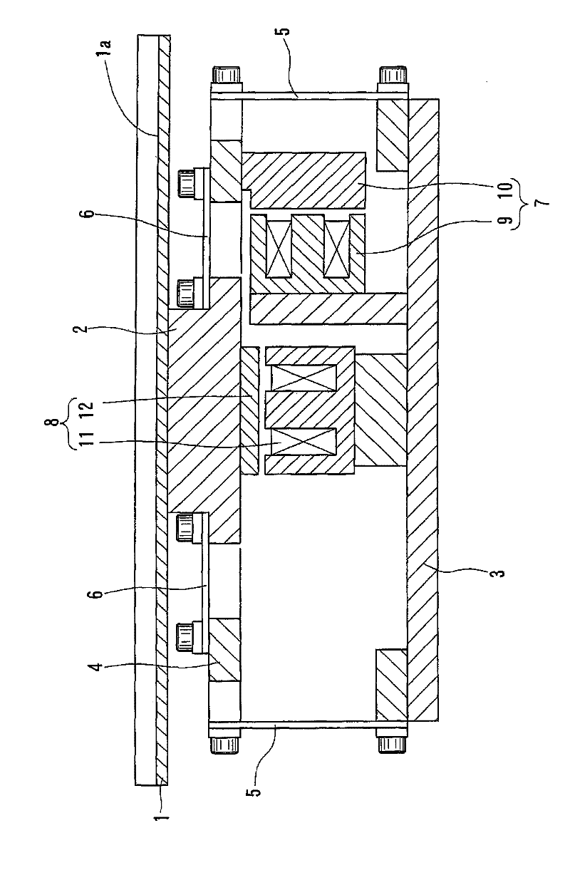
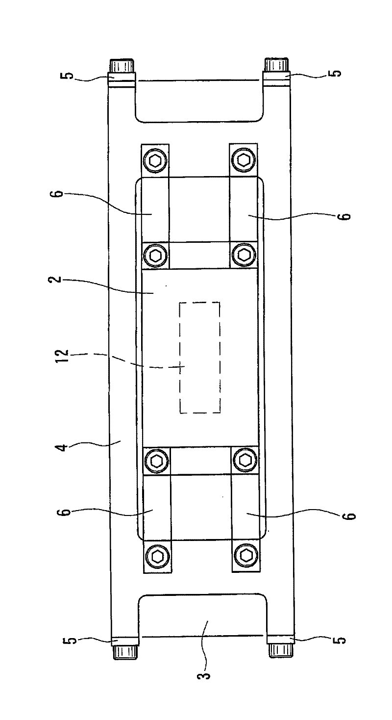
[0039] Below, based on Figure 1 to Figure 13 Embodiments of the present invention will be described. Figure 1 to Figure 7 The first embodiment is shown. Such as figure 1 and figure 2 As shown, the parts conveying device is a vibrating linear feeding device having the following structure: a groove (parts conveying member) 1 formed with a linear conveying path 1a is installed on the upper surface of the upper vibrating body 2, and on the upper part A rectangular frame-shaped intermediate vibrating body 4 is arranged around the vibrating body 2, and the intermediate vibrating body 4 is connected to the base 3 by a first plate spring (elastic member for horizontal vibration) 5 facing the vertical direction, and a second plate spring facing the horizontal direction The plate spring (elastic member for vertical vibration) 6 connects the upper vibrating body 2 and the intermediate vibrating body 4, and the first vibrating mechanism 7 that generates vibration in the horizontal d...


PUM


Abstract

A vibration part feeding apparatus is provided to easily generate vibration suitable for feeding parts by effectively preventing generation of vertical vibration resulting from horizontal vibration. A middle vibration body is connected to an upper vibration body for assembling a groove (a part feeding component) by means of a second plate spring (an elastic component for vertical vibration) facing towards a horizontal direction. The middle vibration body is connected to a base by means of a first plate spring (an elastic component for horizontal vibration) facing towards a vertical direction. When the groove is made to vibration with a natural vibration frequency Fh of the horizontal direction, the amplitude Vv of vertical vibration generated by the groove is over 6dB smaller than the amplitude Vh of the horizontal vibration generated by the groove. Accordingly, the amplitude of vertical vibration resulting from the horizontal vibration of the groove can be reduced, and the desired vibration suitable for parts moving can be easily achieved.

Description

technical field [0001] The present invention relates to a vibrating type component conveying device which vibrates a component conveying member by driving a vibrating mechanism to convey components. Background technique [0002] In the vibrating parts conveying device, there is one that can adjust the vibration in the horizontal direction and the vibration in the vertical direction of the parts conveying member for the purpose of applying the vibration most suitable for parts conveying to the parts conveying member. Structured compound vibration type parts conveying device (for example, refer to Patent Document 1.). [0003] As a component conveying device of the composite vibration type as described above, there is a component conveying device having the following structure: for example, as an embodiment of the present invention, figure 1 as well as figure 2 As shown in the linear feeder (feeder), a rectangular frame-shaped intermediate vibrating body 4 is arranged aroun...

Claims


Application Information

Patent Timeline
Patent Type & Authority Applications(China)
IPC IPC(8): B65G27/16
CPCB65G27/02B65G27/18B65G27/24B65G27/32
Inventor 石河智海尾崎孝美
Owner NTN CORP
Why Eureka
Try Eureka