Miniature pile model used for model tests and manufacturing method thereof

A manufacturing method and technology of micro-pile, which is applied in the preparation of test samples, the test of foundation structure, construction, etc., can solve the difficulty of realizing monitoring components, the inability to monitor the stress of micro-pile, and the inability to obtain the internal force distribution law of micro-pile and damage modes

Inactive Publication Date: 2012-07-04
INST OF GEOMECHANICS
View PDF6 Cites 18 Cited by
  • Summary
  • Abstract
  • Description
  • Claims
  • Application Information

AI Technical Summary

Problems solved by technology

[0004] The field test is the most realistic, but there are also some shortcomings, mainly as follows: 1. The actual micro-piles are constructed through the process of drilling-inserting steel cages-pressure grouting. Due to the small and deep hole diameter, pressure boxes, etc. The layout of the monitoring components is difficult to realize, so the stress of the micropile cannot be monitored; 2. The actual engineering is for the purpose of prevention and control, and a certain safety factor is given in the design, so the landslide is in a stable state after the construction of the micropile. The data of the monitoring components basically does not change much, and the internal force distribution and failure mode of the micro-pile cannot be obtained

Method used


Image

  • Miniature pile model used for model tests and manufacturing method thereof
  • Miniature pile model used for model tests and manufacturing method thereof
  • Miniature pile model used for model tests and manufacturing method thereof

Examples


Embodiment Construction

[0019] For further elaborating the technical means and effect that the present invention takes to reach the intended invention purpose, below in conjunction with accompanying drawing and preferred embodiment, to the miniature pile model that proposes according to the present invention and its manufacturing method for model test and its specific implementation Mode, structure, feature and effect thereof are as follows in detail.

[0020] The concrete steps of this method include:

[0021] (1) Determination of the parameters of the micropile model.

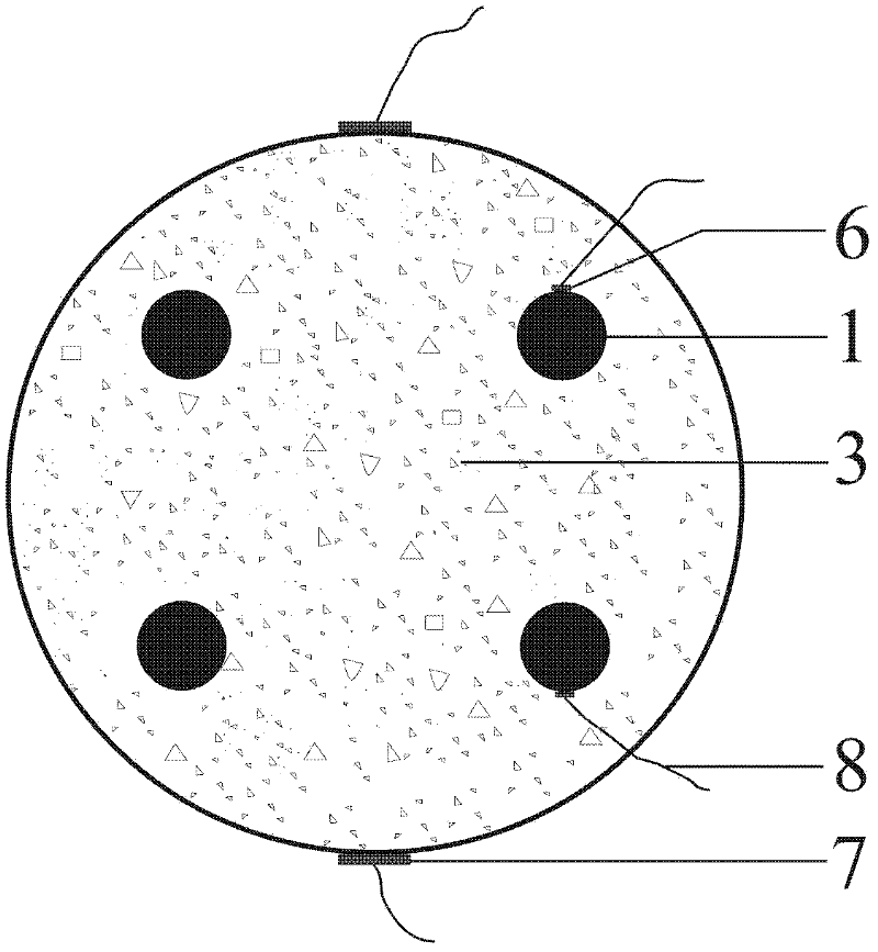
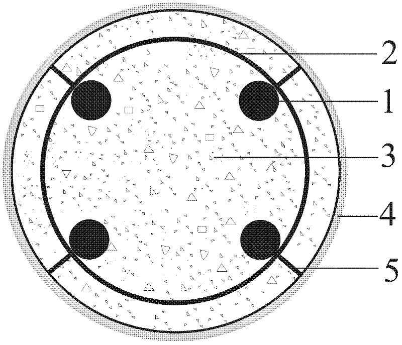
[0022] The parameters of the micro-pile prototype to be studied are: pile length L=12m, pile diameter D=300mm; the reinforcement uses 6 steel bars with a diameter of d=28mm in the form of a steel cage; the pile body is poured with cement mortar.

[0023] According to the test conditions, determine the pile length L'=2m of the micro-pile model in the test, then the geometric similarity ratio C L =L / L'=6. Determine the material of ...


PUM

PropertyMeasurementUnit
diameteraaaaaaaaaa
diameteraaaaaaaaaa

Abstract

The invention relates to a miniature pile model used for model tests and a manufacturing method thereof. The miniature pile model used for tests comprises a steel reinforcing cage and a grouting cylinder, the steel reinforcing cage comprises a plurality of longitudinal main reinforcing bars and hooping reinforcing bars, the main reinforcing bars are connected transversely through the hooping reinforcing bars, and the steel reinforcing cage is coated by the grouting cylinder, each main reinforcing bar of the steel reinforcing cage is provided with at least one strain piece, the strain pieces are provided with leads which extend out of the grouting cylinder, and at least one strain piece is arranged on the outer wall of the grouting piece. The manufacturing method of the miniature pile model includes: determining parameters of the miniature pile model, preparing the steel reinforcing cage, setting the strain pieces on the steel reinforcing cage, disposing the steel reinforcing cage into a mould, injecting grouting materials into the mould, maintaining the grouting materials to form the grouting cylinder and setting the strain pieces on the outer wall of the grouting cylinder. Internal structures of the miniature pile model and the original body are identical, and test results including failure mode and distribution law of internal force and the like of the miniature pile are more practical.

Description

technical field [0001] The invention relates to a miniature pile model, in particular to a miniature pile model for model testing and a manufacturing method thereof. Background technique [0002] Micropiles refer to bored piles with a diameter of 90-300mm, which were first used in foundation reinforcement, and later gradually applied in landslide prevention and slope reinforcement projects. Due to the advantages of non-excavation construction, small disturbance to the slide body, and fast construction speed, micropiles have been widely used in the prevention and control of side landslides, especially the emergency reinforcement of landslides in recent years. However, due to the relatively short application history of micropiles in landslide prevention and control, people do not fully understand the force and deformation laws of them under the action of landslides. Arranged in the form of pile groups, the mechanism of pile-soil interaction is complex, so there is no recogniz...

Claims


Application Information

Patent Timeline
Patent Type & Authority Applications(China)
IPC IPC(8): E02D33/00G01N1/28
Inventor 闫金凯殷跃平李滨门玉明冯振
Owner INST OF GEOMECHANICS
Why Eureka
Try Eureka