Rotary-cylinder rotor engine

A rotary engine and rotary cylinder technology, which is applied to combustion engines, machines/engines, internal combustion piston engines, etc., can solve the problems of increased fuel and engine oil consumption, the inability to use compression ignition, high cost, etc., and achieve improved intake and exhaust Superposition angle, improved intake and exhaust angle, simple and reliable structure

Inactive Publication Date: 2012-07-04
马驰成
View PDF5 Cites 6 Cited by
  • Summary
  • Abstract
  • Description
  • Claims
  • Application Information

AI Technical Summary

Problems solved by technology

[0007] 2. Compared with the reciprocating engine, the rotary engine has the following disadvantages: (1) The fuel consumption is relatively large
This is mainly because the shape of the combustion chamber of the rotary engine is not conducive to complete combustion, and the flame propagation path is longer, which increases the consumption of fuel and oil
(2) The rotary engine can only use the ignition type, not the compression ignition type, that is, diesel oil cannot be used
(3) The processing and manufacturing technology of the rotary engine is high, the cost is relatively expensive, and it is difficult to promote
[0008] 3. Disadvantages for reciprocating engines: (1) The structure is complex and requires a valve mechanism, including timing belts, camshafts, rocker arms, valves, valve springs, etc.
(2) Larger volume and weight
(3) The torque characteristic curve fluctuates greatly
(4) The noise is high, and the piston and valve mechanism will produce large mechanical noise
(4) There are many moving parts at high speed, which affects reliability and durability

Method used


Image

  • Rotary-cylinder rotor engine
  • Rotary-cylinder rotor engine
  • Rotary-cylinder rotor engine

Examples


Embodiment Construction

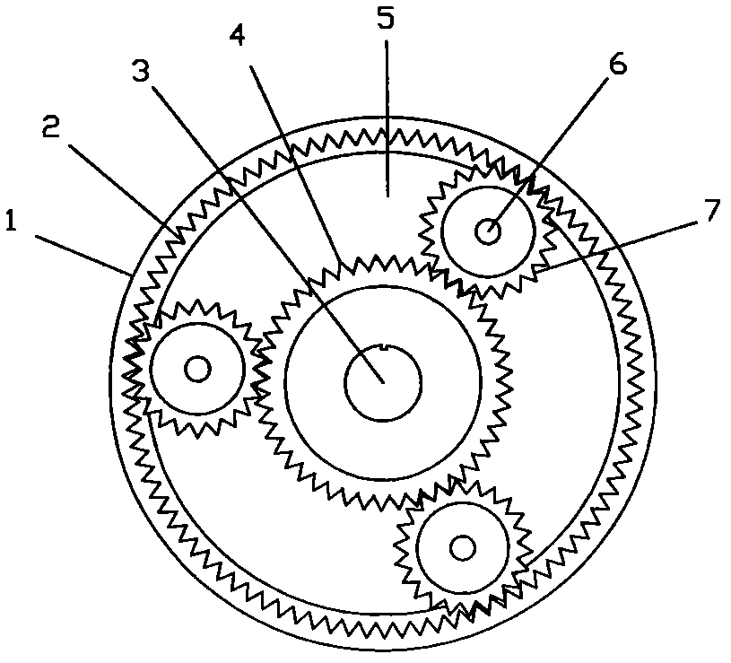
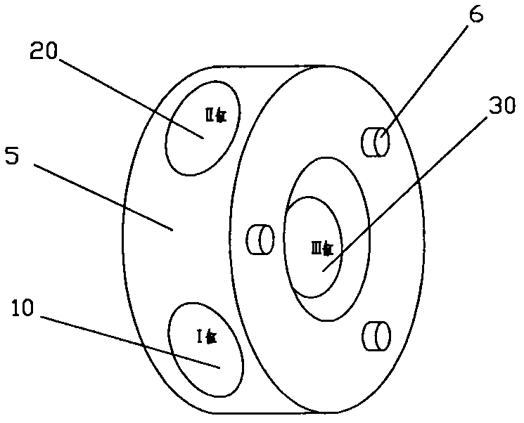
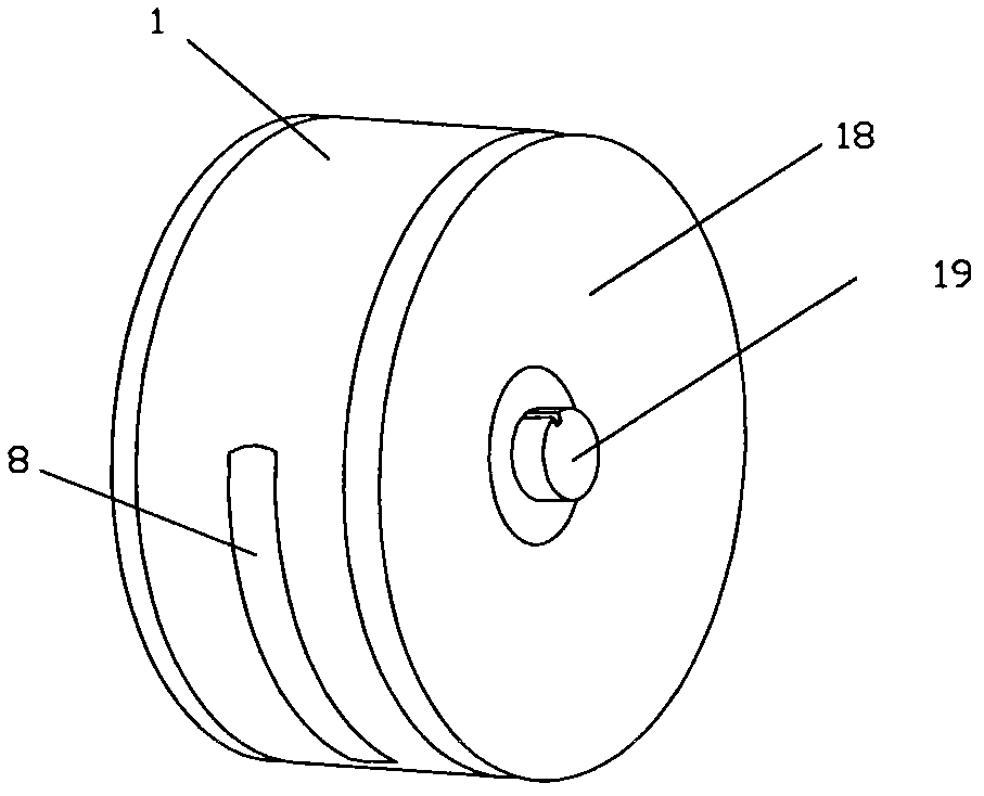
[0018] Such as Figure 1 to Figure 7 As shown, the present invention includes a housing 1 and a rotor 5. The inner wall of the housing 1 is circular, and the housing 1 is provided with an air intake slot 8 and an exhaust slot 15 with a radian of 80° to 100° along the circumferential direction. , the intake notch 8 is adjacent to the exhaust notch 15, and the inner wall of the opposite housing 1 at the adjacent place is provided with a hole for installing the spark plug 16, the intake notch 8 is connected with the carburetor 9, and the exhaust notch 15 Connected with the exhaust pipe, the inner wall of the housing 1 or the end cover is provided with an inner ring gear 2; the rotor 5 is a circular structure, and the rotor 5 is provided with three cylinders 10, 20, 30. There is a piston 11 in the cylinder, a crankshaft 14 and a connecting rod 12 mechanism are installed in the center of the rotor 5, and the crankshaft 14 is installed on the central axis 3 in the center of the roto...


PUM


Abstract

The invention relates to an engine and discloses a rotary-cylinder rotor engine, which comprises a shell and a rotor, and is characterized in that: the inner wall of the shell is round, an air-inlet notch and an air-discharging notch are arranged on the shell along a circumferential direction, the inner wall of the shell is provided a hole for installing a spark plug, and an inner gear ring is arranged in an end cover on the lateral surface of the shell; the rotor is of an annular structure, three cylinder bodies which are in star-shaped uniform distribution at an angle of 120 degrees are arranged in the rotor, a piston is arranged in each cylinder body, a crankshaft connecting-rod mechanism is installed at the center of the rotor, one ends of three connecting rods are installed on a connecting-rod pin on a crankshaft, and the other ends of the three connecting rods are respectively connected with the three pistons in the rotor; and the rotor is driven to rotate along the same direction by the crankshaft through a transmission mechanism. The rotary-cylinder rotor engine has the advantages of simple and reliable structure, intensity work doing, high power, small size, low oil consumption, small noise and small vibration and can be used for replacing ordinary reciprocating-type engines and rotor engines.

Description

technical field [0001] The invention relates to an engine, in particular to a rotary engine. Background technique [0002] There are two main types of engines: reciprocating engines and rotary engines, both of which rely on the expansion pressure generated by the combustion of air-fuel mixture to obtain rotational force. The difference lies in the way the expansion pressure is used. In a reciprocating engine, the expansion pressure generated on the top surface of the piston pushes the piston down. The mechanical force is transmitted to the connecting rod, which turns the crankshaft. In the case of a rotary engine, expansion pressure acts on the side of the rotor, thereby pushing one of the three faces of the triangular rotor towards the center of the eccentric shaft, this movement takes place under the force of two components, one pointing towards the center of the output shaft The centripetal force, and the other is the tangential force that turns the output shaft. The in...

Claims


Application Information

Patent Timeline
Patent Type & Authority Applications(China)
IPC IPC(8): F02B57/08F02B61/06
Inventor 马驰成
Owner 马驰成
Why Eureka
Try Eureka