
Method and system for solving problem of exhaust gas recirculation (EGR) drive hysteresis

A hysteresis and engine technology, applied in the direction of engine control, machine/engine, mechanical equipment, etc., can solve problems such as inconsistent strokes, affecting the recirculation effect of the exhaust gas recirculation system, EGR drive hysteresis, etc.

Active Publication Date: 2012-07-04
WEICHAI POWER CO LTD
View PDF4 Cites 11 Cited by
  • Summary
  • Abstract
  • Description
  • Claims
  • Application Information

AI Technical Summary

Problems solved by technology

This is because, when the duty cycle changes from large to small and from small to large, the opening and closing directions of the EGR valve are opposite. Due to the existence of friction and mechanical clearance, under the same value of duty cycle control, the EGR valve will open and close in the opposite direction. The strokes in the closing direction are not consistent, resulting in driving hysteresis, resulting in a large deviation between the final opening of EGR and the required opening, affecting the recirculation effect of the exhaust gas recirculation system
[0006] In view of this, how to avoid the phenomenon of EGR drive hysteresis when the duty cycle changes from large to small or from small to large is a technical problem to be solved by those skilled in the art.

Method used


Image

  • Method and system for solving problem of exhaust gas recirculation (EGR) drive hysteresis
  • Method and system for solving problem of exhaust gas recirculation (EGR) drive hysteresis
  • Method and system for solving problem of exhaust gas recirculation (EGR) drive hysteresis

Examples


Embodiment Construction

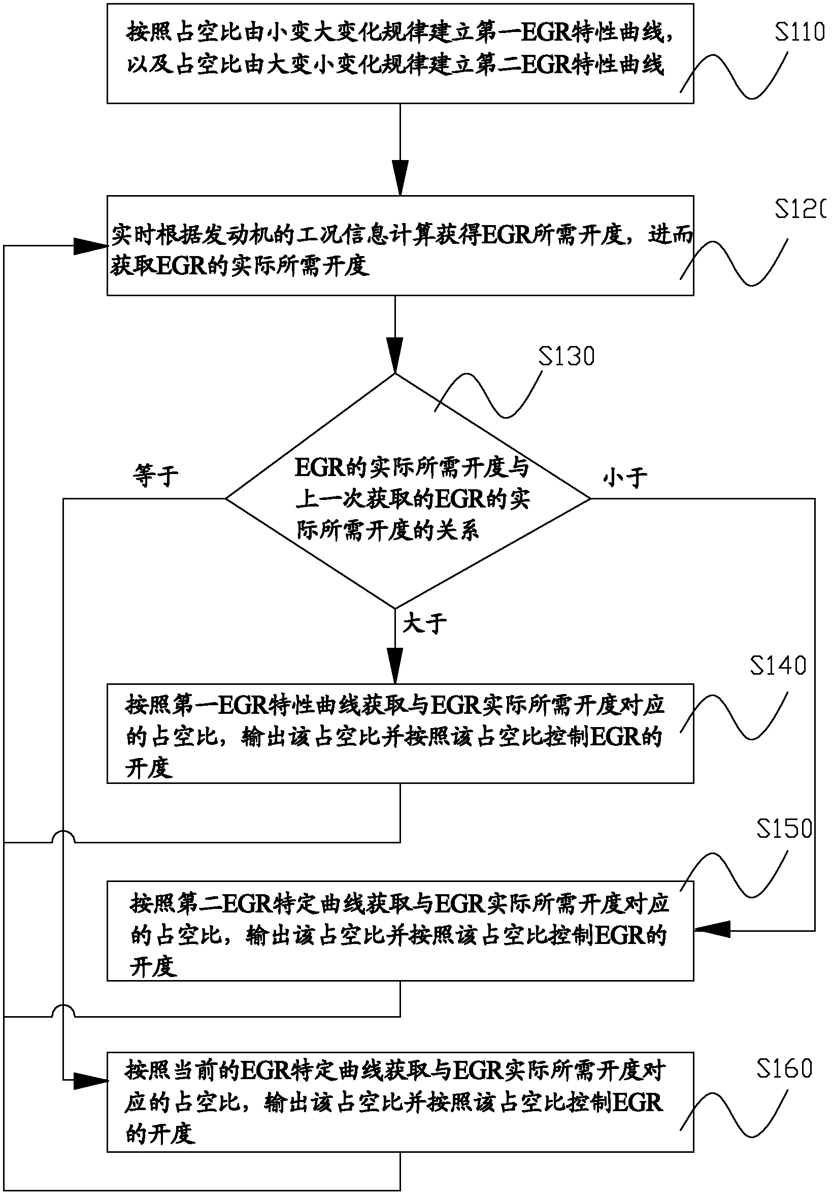
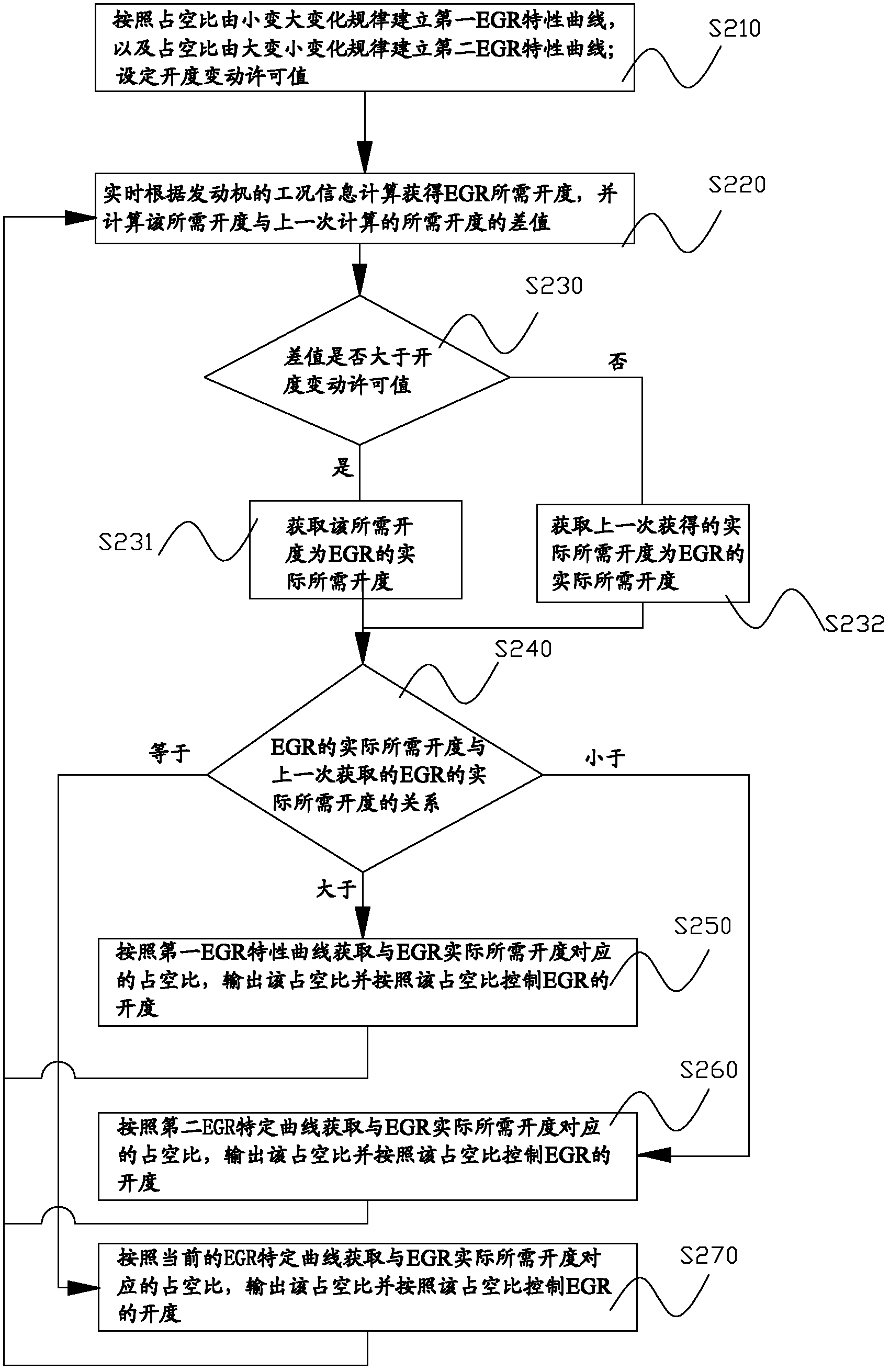
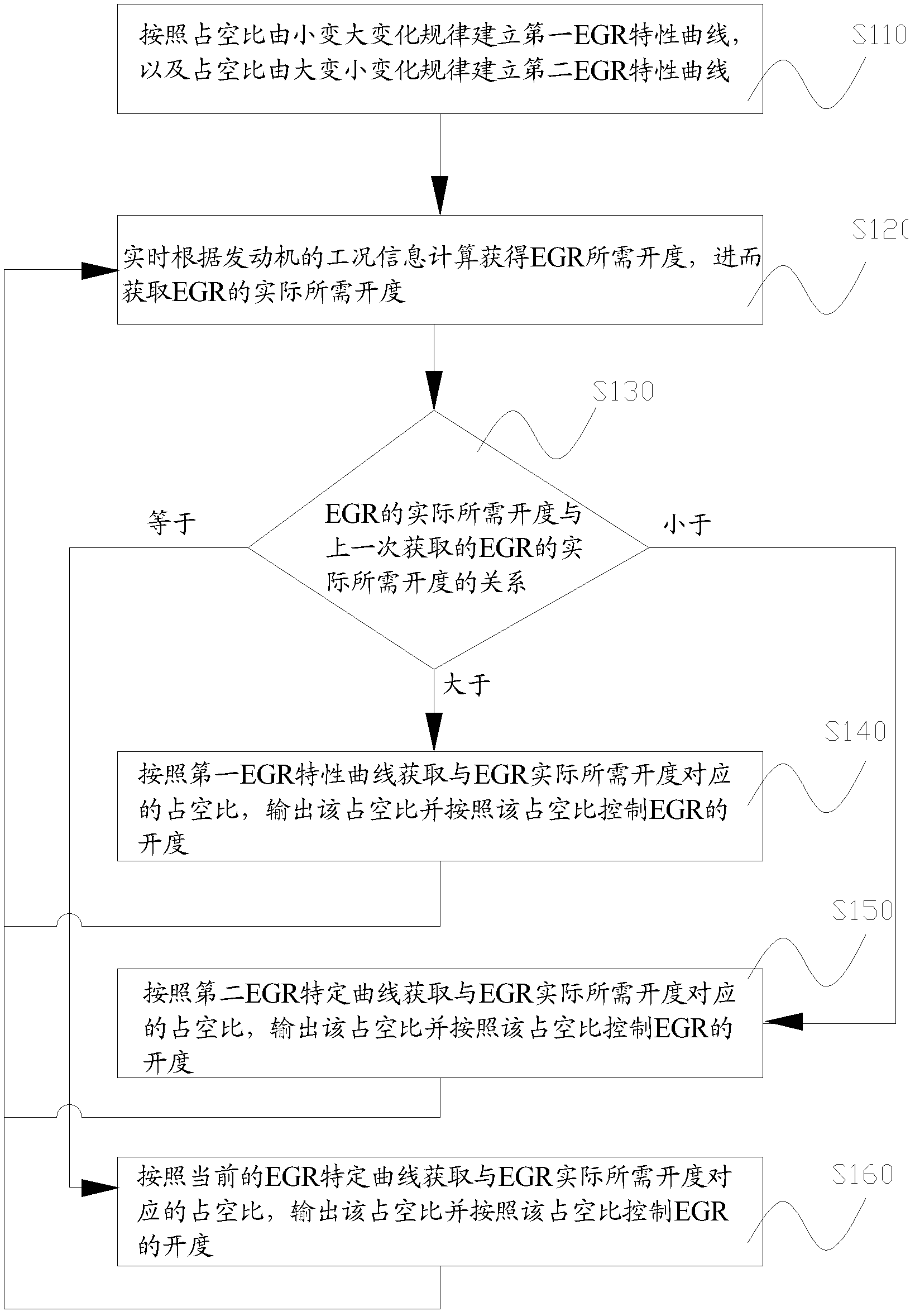
[0029] The core of the present invention is to provide a method and system for solving EGR driving hysteresis, which can avoid the hysteresis phenomenon that occurs when the duty ratio changes from large to small or from small to large.

[0030] In order to enable those skilled in the art to better understand the technical solutions of the present invention, the present invention will be further described in detail below in conjunction with the accompanying drawings and specific embodiments. For ease of understanding and brevity of description, the method and system for solving the EGR driving hysteresis will be described below, and the beneficial effects will not be discussed repeatedly.

[0031] The system to solve the EGR driving hysteresis mainly includes: storage unit, acquisition unit, analysis unit and execution unit. The main operation process of the system can be understood in conjunction with the following content.

[0032] Please refer to figure 1 , figure 1 It i...


PUM


Abstract

The invention discloses a method and a system for solving the problem of exhaust gas recirculation (EGR) drive hysteresis. The method includes the following steps: establishing a first EGR characteristic curve and a second EGR characteristic curve according to the tendency that EGR opening degree becomes smaller and the tendency that EGR opening degree becomes bigger; obtaining the required opening degree of EGR in real-time calculation mode, and obtaining the actually required opening degree of EGR; and when the actually required opening degree of EGR is bigger than the value of last time, working according to the first EGR characteristic curve, when the actually required opening degree of EGR is smaller than the value of last time, working according to the second EGR characteristic curve, and when the actually required opening degree of EGR is equal to the value of last time, working according to a current EGR characteristic curve. The method and the system lead to the fact that the first EGR characteristic curve is followed when the EGR opening degree needs to be increased, and the second EGR characteristic curve is followed when the EGR opening degree needs to be decreased. Therefore, the variation tendency of the actually required opening degree of EGR is consistent to the variation tendency when the EGR characteristic curves are established, and the phenomenon of EGR drive hysteresis caused by inconsistency of the variation tendencies is removed.

Description

technical field [0001] The invention relates to the technical field of engines, in particular to a method and system for solving EGR driving hysteresis. Background technique [0002] The engine is a device that converts the chemical energy of fuel into mechanical energy. The combustion of fuel needs to be mixed with air in a certain proportion. In order to meet the national emission regulations, the engine needs to reduce the nitrogen oxide content in the exhaust gas. The EGR system (Exhaust Gas Recirculation, exhaust gas recirculation system) can reintroduce the exhaust gas into the intake system, thereby using the carbon dioxide in the exhaust gas to reduce the combustion temperature in the cylinder. , thereby inhibiting the formation of nitrogen oxides and meeting emission regulations. [0003] Of course, the EGR rate must be limited to a certain extent, otherwise too much exhaust gas entering the combustion chamber may worsen the emissions of hydrocarbons, carbon monoxi...

Claims


Application Information

Patent Timeline
IPC IPC(8): F02D21/08
Inventor 刘兴义李大明胡广地
Owner WEICHAI POWER CO LTD
Learn More