Supercharge Your Innovation With Domain-Expert AI Agents!

Gas storage tank comprising a liquid sealant

A fluid sealing material and gas storage technology, applied in gas processing/storage purposes, gas/liquid distribution and storage, fluid processing, etc., can solve problems such as hydrogen leakage, sealing adhesive deterioration, damage, etc.

Active Publication Date: 2012-07-04
GM GLOBAL TECH OPERATIONS LLC
View PDF6 Cites 10 Cited by
  • Summary
  • Abstract
  • Description
  • Claims
  • Application Information

AI Technical Summary

Problems solved by technology

Under such working conditions, O-rings and sealing adhesives will deteriorate and may be damaged, which leads to hydrogen leakage

Method used


Image

  • Gas storage tank comprising a liquid sealant
  • Gas storage tank comprising a liquid sealant

Examples


Embodiment Construction

[0035] The following descriptions of the embodiments are for explanation only, and cannot be used to limit the present invention and its application or use.

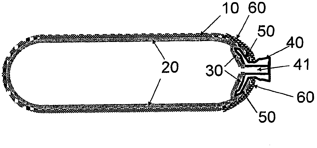
[0036] In high pressure applications, gas storage tanks can be configured as spherical or cylindrical, usually with hemi-spherical ends (domes), although other tank geometries are possible. The tank may comprise an inner bladder formed by an airtight inner liner layer, which is protected by an outer structural layer. The boss can be used to reliably connect the inner liner and the outer structural layer at the booster valve port of the tank shell to prevent gas leakage between the liner and the shell. There may be more than one boss in the gas storage tank. Typically there is a bore section within the boss to provide safe and reliable gas communication with the inflation source, gas consumer and pressure / temperature sensor.

[0037] figure 1 is a sectional view of a gas storage tank according to one embodiment of the ...


PUM


Abstract

One exemplary embodiment includes a gas storage tank comprising a structural outer layer, an internal liner layer, an annular boss, and a liquid sealant disposed between the overlapped section of the liner layer and the boss to provide a gas-tight seal.

Description

technical field [0001] The technical field of the invention relates generally to gas storage tanks including fluidic sealing materials. Background technique [0002] Various fuel gases, such as natural gas, hydrogen, acetylene and methane, can be stored in pressurized gas storage tanks. To increase the storage density and reduce the weight of the overall system, a tank design with high working gas pressure and light weight is required. For the storage of pressurized hydrogen, special attention needs to be paid to tank design and material selection because hydrogen is highly permeable to most materials and many common metals are known to be hydrogen brittle. In addition, the ignition potential of hydrogen is much higher than that of methane. Theoretically, hydrogen is about 34 times more permeable than methane. Infiltration and leakage were identified as major concerns. Compressed hydrogen fuel tanks for vehicle fuel cells can have pressures as high as 700 bar (~70 MPa). ...

Claims


Application Information

Patent Timeline
IPC IPC(8): F17C1/00F17C13/00
CPCY02E60/321F17C2203/0619F17C2260/011F17C2209/234F17C2205/0196F17C2209/2145F17C2209/2127F17C2203/0663F17C2250/0439F17C2205/0338F17C2203/0621F17C2201/056F17C2250/0491F17C2270/0184F17C2205/0394F17C2209/2118F17C2203/066F17C2270/0168F17C2203/0682F17C2201/0109F17C2205/0305F17C2209/2154F17C2203/0675F17C2250/043F17C2223/036F17C2203/0648F17C1/06F17C2260/036F17C2201/0128F17C2221/018F17C2221/033F17C2221/012F17C2203/0646F17C2209/221F17C1/16F17C2223/0123F17C2203/0604F17C2209/219Y02E60/32Y10T29/49826
Inventor M·林纳D·A·波多拉施A·荣格
Owner GM GLOBAL TECH OPERATIONS LLC
Features
  • R&D
  • Intellectual Property
  • Life Sciences
  • Materials
  • Tech Scout
  • Unparalleled Data Quality
  • Higher Quality Content
  • 60% Fewer Hallucinations
Learn More