Oscillating mechanism for fan heater

A technology for heaters and synchronous motors, used in lighting and heating equipment, fluid heaters, etc., can solve the problems of not being able to protect the power cord well, and difficult to pass 750,000 shaking head tests, to improve service life and reduce wear and tear. Effect

Inactive Publication Date: 2012-07-04
GD MIDEA ENVIRONMENT APPLIANCES MFG +1
View PDF4 Cites 12 Cited by
  • Summary
  • Abstract
  • Description
  • Claims
  • Application Information

AI Technical Summary

Problems solved by technology

[0002] The existing oscillating mechanisms of heaters are mostly cranks, connecting rod mechanisms, gears, and racks. These traditional oscillating mechanisms cannot protect the power cord well when they work, and it is difficult to pass the 750,000 shaking head tests.

Method used


Image

  • Oscillating mechanism for fan heater
  • Oscillating mechanism for fan heater
  • Oscillating mechanism for fan heater

Examples


Embodiment Construction

[0013] The present invention will be further described below in conjunction with the accompanying drawings and embodiments.

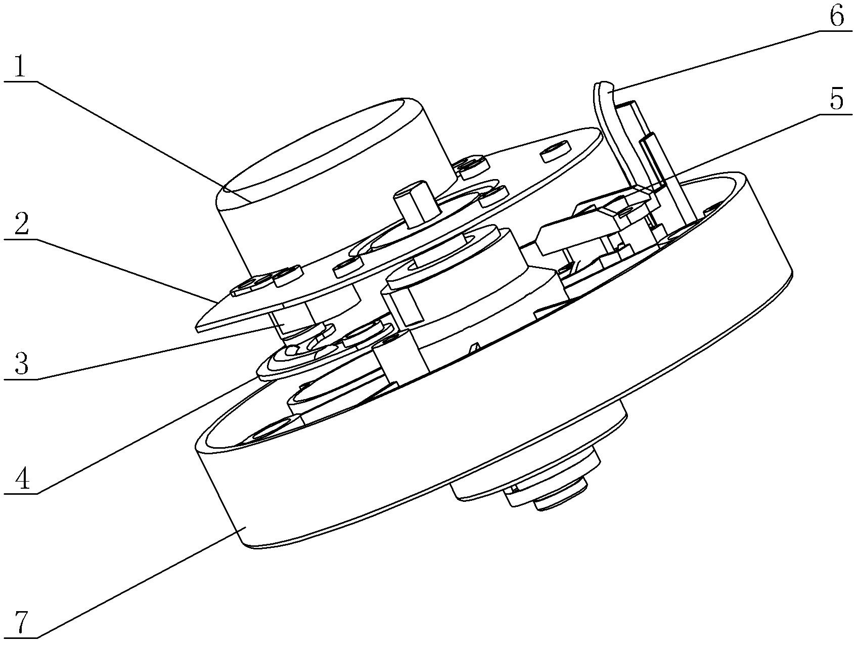
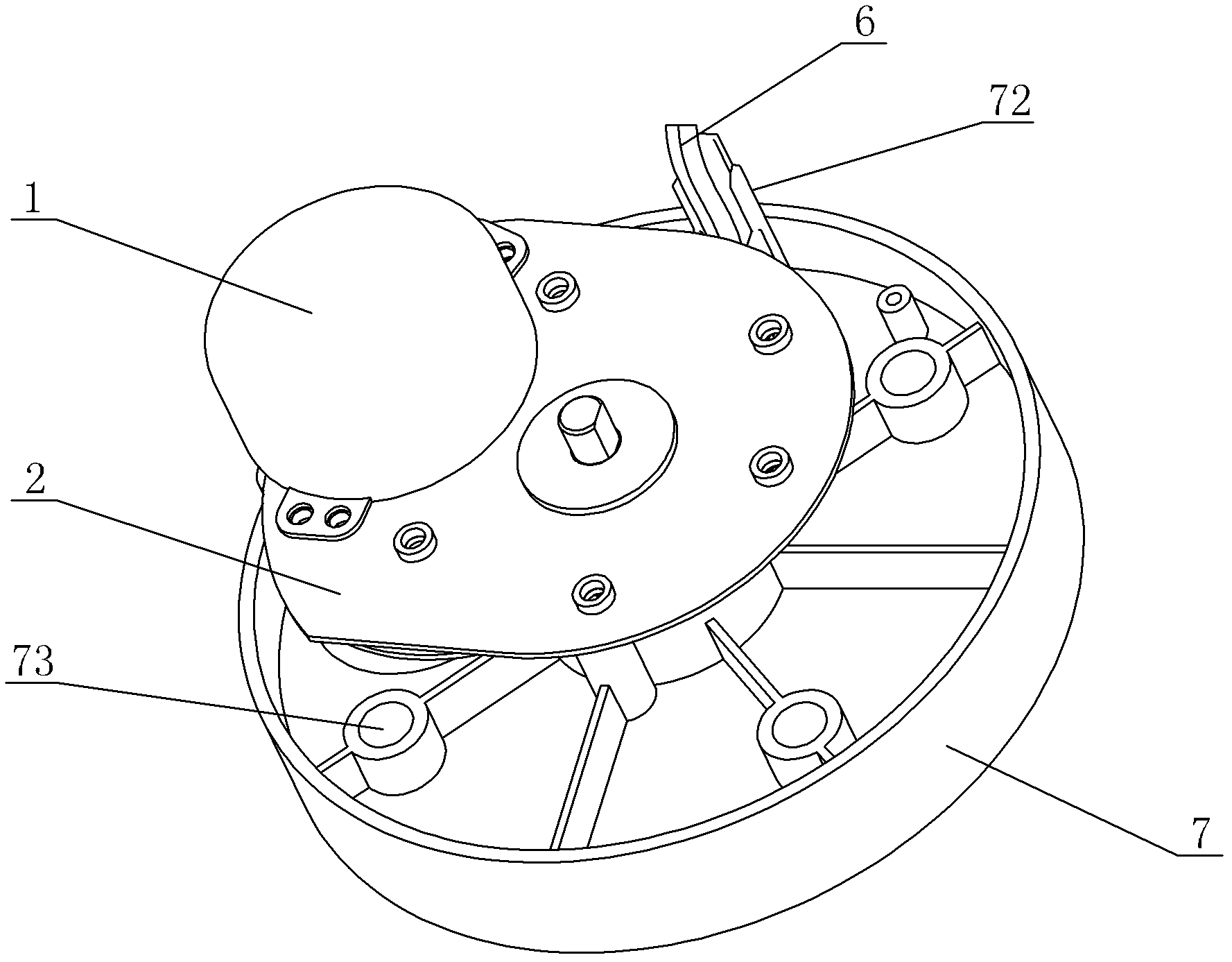
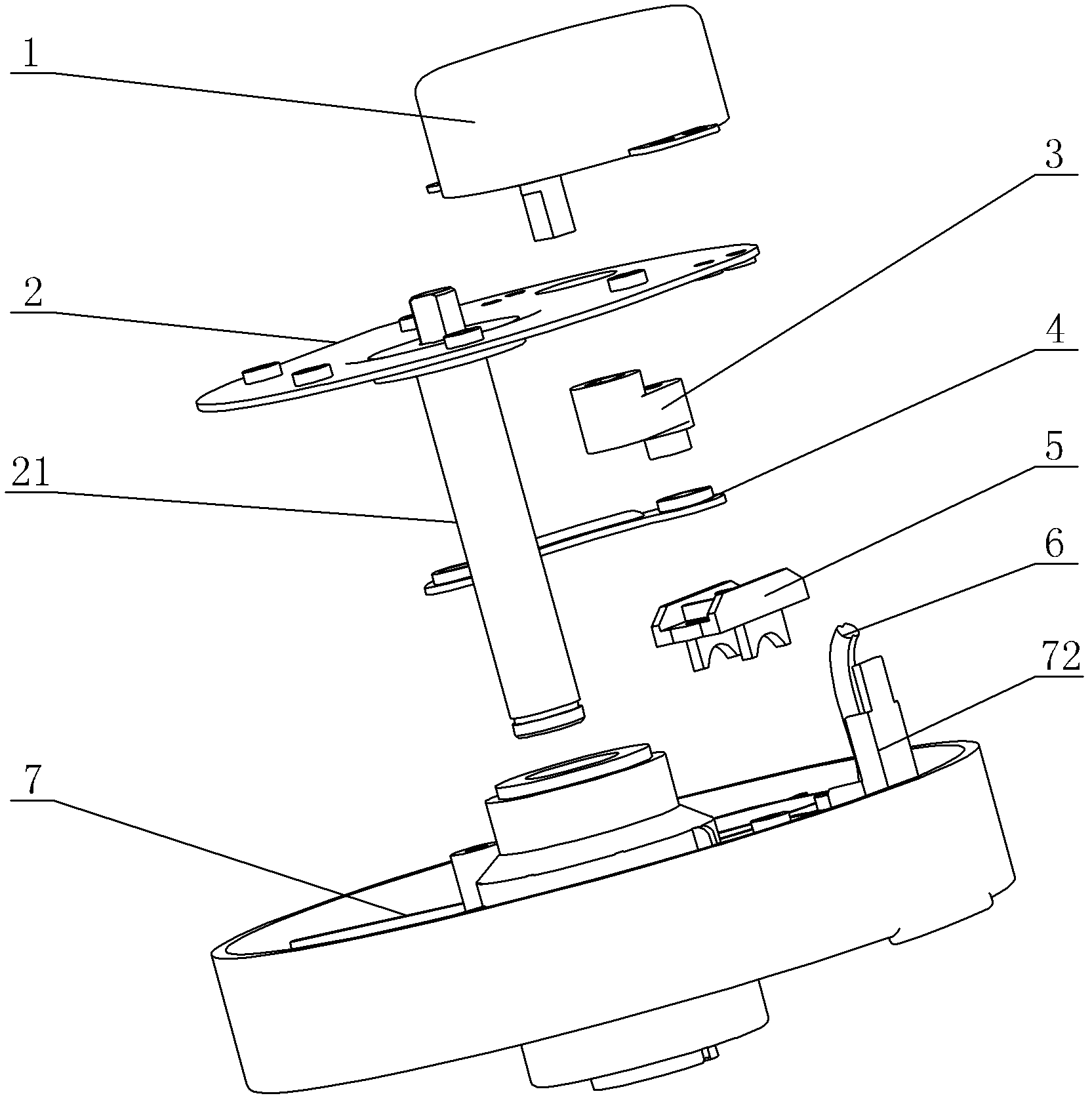
[0014] see Figure 1-Figure 4 , a heater shaking head mechanism, including a synchronous motor 1, a vertical shaft assembly 2, a crank 3, a connecting rod 4 and a power cord 6, wherein the synchronous motor 1 is fixed on the vertical shaft assembly 2, and the two ends of the crank 3 are respectively connected to the synchronous motor 1 and the One end of the connecting rod 4 is rotatably connected, and also includes an oscillating chassis 7 connected to the other end of the connecting rod 4 and a crimping box 5 installed on the oscillating chassis 7, and the power cord 6 is fixed on the oscillating chassis 7 through the crimping box 5. The oscillating head chassis 7 is installed on the vertical shaft 21 of the vertical shaft assembly 2, and the oscillating head chassis 7 takes the vertical shaft 21 as the rotation center. A plurality of nuts 73 for in-...


PUM


Abstract

The invention discloses an oscillating mechanism for a fan heater. The oscillating mechanism comprises a synchronous motor, a vertical shaft component, a crank, a connecting rod and a power line, wherein the synchronous motor is fixed on the vertical shaft component; two ends of the crank are rotationally connected with the synchronous motor and one end of the connecting rod respectively; and the oscillating mechanism is characterized by also comprising an oscillating base plate connected with the other end of the connecting rod; the power line is fixed on the oscillating base plate through a protection structure arranged on the oscillating base plate; the protection structure comprises a crimping box arranged on the oscillating base plate; a crimping box bolt column is arranged on the oscillating base plate corresponding to the crimping box; and the oscillating mechanism also comprises wire through holes and a wire blocking structure. Due to the adoption of the oscillating base plate of the oscillating mechanism, the oscillating base plate comprises a structure for protecting the power line; and therefore, wear of the power line during oscillating is greatly reduced, the service life of the oscillating mechanism is prolonged, and 750000 oscillating tests are ensured to be passed.

Description

technical field [0001] The invention relates to a head-shaking mechanism of a heater, which belongs to the transformation technology of the head-shaking mechanism of a heater. Background technique [0002] The oscillating mechanisms of existing heaters are mainly cranks, connecting rod mechanisms, gears, and racks. These traditional oscillating mechanisms cannot protect the power cord well during operation, and it is difficult to pass the 750,000 shaking head tests. Therefore, it is necessary to further improve and perfect. Contents of the invention [0003] The object of the present invention is to provide a heater shaking mechanism with simple structure, low cost, stable shaking performance and long service life, so as to overcome the shortcomings in the prior art. [0004] According to this purpose, a heater shaking head mechanism includes a synchronous motor, a vertical shaft assembly, a crank, a connecting rod and a power cord, wherein the synchronous motor is fixed ...

Claims


Application Information

Patent Timeline
Patent Type & Authority Applications(China)
IPC IPC(8): F24H9/00
Inventor 王庆袁新南谭成波
Owner GD MIDEA ENVIRONMENT APPLIANCES MFG
Why Eureka
Try Eureka