Rotary encoder

A technology of rotary encoders and encoder discs, applied in the field of encoders, can solve the problems of encoders not being able to move, the number of pulses is limited, and the measurement accuracy is not high, so as to meet the requirements of high-precision and high-speed measurement and improve the reliability of data Effect

Active Publication Date: 2013-08-07
CHONGQING PURE SMART SCI & TECH CO LTD
View PDF4 Cites 1 Cited by
  • Summary
  • Abstract
  • Description
  • Claims
  • Application Information

AI Technical Summary

Problems solved by technology

In this way, when the power is cut off, the encoder cannot move in any way, and when the power is on, the encoder cannot lose pulses due to interference during the pulse output process, otherwise, the zero point of the counting device memory will shift, and this deviation There is no way to know the amount of displacement, only after the wrong production results appear
Also, incremental pulses are virtual, and the number of pulses collected is limited, so the measurement accuracy is not high
On the other hand, the structure of the rotary incremental encoder is more complicated

Method used


Image

  • Rotary encoder
  • Rotary encoder
  • Rotary encoder

Examples


Embodiment Construction

[0023] Below in conjunction with accompanying drawing and embodiment the present invention will be further described:

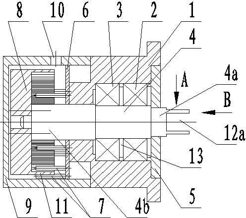
[0024] Such as Figure 1 to Figure 5 As shown, a rotary encoder includes a bearing housing 1, and the bearing housing 1 supports a rotating shaft 4 through first bearings 2 and second bearings 3 arranged at intervals. A bearing retaining ring 13 is arranged between the first bearing 2 and the second bearing 3.

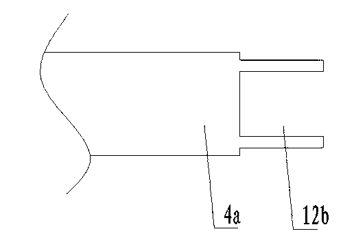
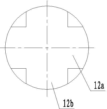
[0025] An end cover 5 is fixedly connected to the first end of the bearing housing 1 , and a circuit board 6 is fixedly connected to the end surface of the second end. The rotating shaft 4 is provided with a first connection groove 12a and a second connection groove 12b perpendicular to each other at the protruding end 4a of the end cover 5, so as to clamp it on the shaft parts of the rotating machine, and the encoder can be synchronized with it after being fixed. rotate.

[0026] In this embodiment, the circuit board 6 is directly fixedly connecte...


PUM


Abstract

The invention discloses a rotary encoder, which includes a bearing pedestal, wherein the bearing pedestal is used for supporting a rotating shaft through a first bearing and a second bearing which are arranged at an interval; an end cover and a circuit board are fixed with the bearing pedestal; M pairs of photoelectric sensors are arranged at the circuit board at intervals in the circumferential direction; each pair of photoelectric sensors are arranged at an interval in the radial direction of the circuit board; the rotating shaft penetrates the circuit board, and a coding disk correspondingto the circuit board is fixed at the end of the rotating shaft penetrating through the circuit board; N light shielding blocks are uniformly distributed on the edge of the coding disk in the circumferential direction; when the coding disk is rotated, the light shielding blocks can pass by the radial interval of each pair of the photoelectric sensors; the included angle between the two adjacent pairs of photoelectric sensors meets the condition of the formula X equals to a*360 / N +1, wherein the X is the included angle, a is a natural number, and N equals to the amount of the light shielding blocks; the bearing pedestal is provided with a sealing cover positioned on one side of the coding disk; the circuit board and the coding disk are positioned in the sealing cover; and a conducting wire via hole is formed in the sealing cover. The rotary encoder provided by the invention greatly improves the characteristics of antijamming and data reliability, and can meet the requirement for high-precision and high rotational speed measurement.

Description

technical field [0001] The invention relates to an encoder, in particular to a rotary encoder for measuring the high-precision rotating speed of a mechanical shaft. Background technique [0002] In the prior art, an encoder for measuring the rotational speed of a mechanical shaft is generally an incremental encoder. The incremental encoder converts the displacement into a periodic electrical signal, and then converts the electrical signal into a counting pulse, and uses the number of pulses to represent the magnitude of the displacement. Rotate the incremental encoder to output pulses when turning, and know its position through the counting device. When the encoder does not move or the power fails, it relies on the internal memory of the counting device to remember the position. In this way, when the power is cut off, the encoder cannot move in any way, and when the power is on, the encoder cannot lose pulses due to interference during the pulse output process, otherwise, t...

Claims


Application Information

Patent Timeline
Patent Type & Authority Patents(China)
IPC IPC(8): G01P3/486
Inventor 邓黎明藤志远乔明春
Owner CHONGQING PURE SMART SCI & TECH CO LTD
Why Eureka
Try Eureka