Optical imaging lens group
A lens group and lens technology, applied in optics, optical components, instruments, etc., can solve problems such as unsatisfactory photography lens modules, and achieve the effects of reducing system sensitivity, high resolution, and large viewing angle
- Summary
- Abstract
- Description
- Claims
- Application Information
AI Technical Summary
Problems solved by technology
Method used
Image
Examples
Embodiment 1
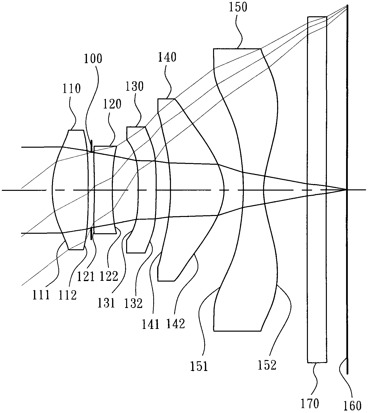
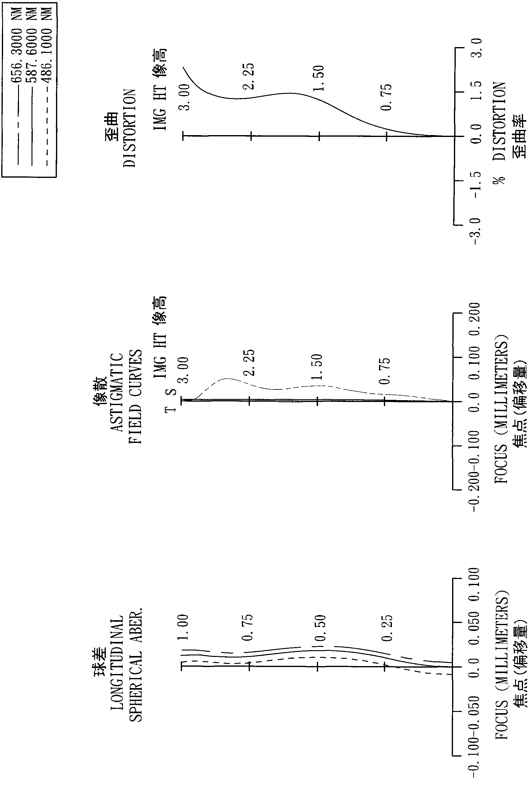
[0155] In the optical imaging lens group of embodiment 1, the focal length of the overall optical imaging lens group is f, the aperture value (f-number) of the overall optical imaging lens group is Fno, half of the maximum viewing angle in the overall optical imaging lens group is HFOV, and its relationship is:
[0156] f=3.83mm;
[0157] Fno=2.70;
[0158] HFOV=37.6 degrees.
[0159] In Embodiment 1, the dispersion coefficient of the first lens 110 is V1, the dispersion coefficient of the second lens 120 is V2, and the dispersion coefficient of the third lens 130 is V3, and the relationship is as follows:
[0160] V1-V2=32.5;
[0161] |V2-V3|=0.0.
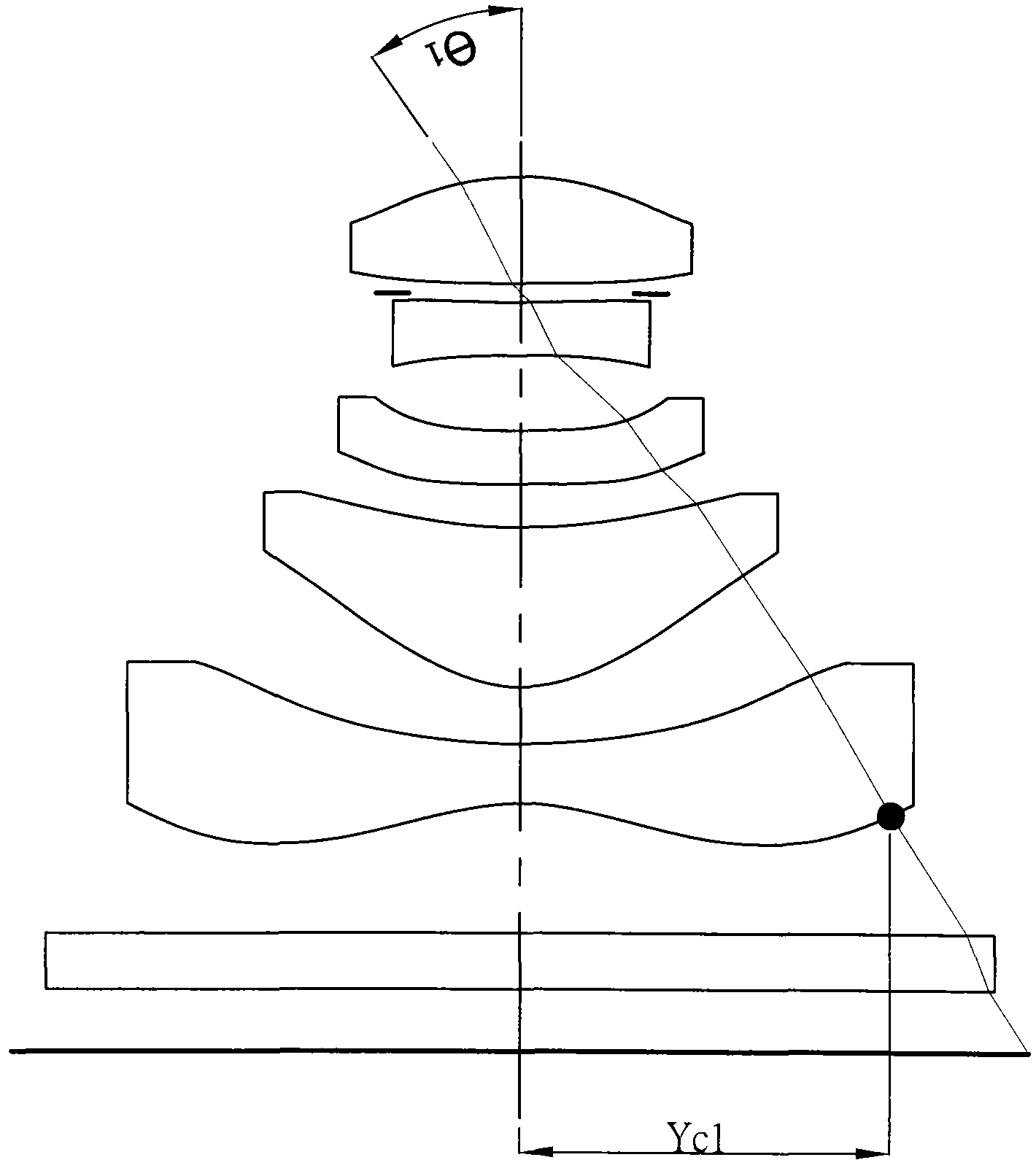
[0162] In Embodiment 1, the radius of curvature of the object-side surface 111 of the first lens 110 is R1, the radius of curvature of the image-side surface 112 is R2, the radius of curvature of the object-side surface 121 of the second lens 120 is R3, and the radius of curvature of the image-side surface 122 is R4 , the rad...
Embodiment 2
[0192] The curve equation of the aspheric surface in embodiment 2 is expressed in the form of embodiment 1.
[0193] In the optical imaging lens group of embodiment 2, the focal length of the overall optical imaging lens group is f, the aperture value (f-number) of the overall optical imaging lens group is Fno, half of the maximum viewing angle in the overall optical imaging lens group is HFOV, and its relationship is:
[0194] f=3.83mm;
[0195] Fno=2.70;
[0196] HFOV=37.4 degrees.
[0197] In Embodiment 2, the dispersion coefficient of the first lens 210 is V1, the dispersion coefficient of the second lens 220 is V2, and the dispersion coefficient of the third lens 230 is V3, and the relationship is as follows:
[0198] V1-V2=34.4;
[0199] |V2-V3|=2.0.
[0200] In Embodiment 2, the radius of curvature of the object-side surface 211 of the first lens 210 is R1, the radius of curvature of the image-side surface 212 is R2, the radius of curvature of the object-side surfa...
Embodiment 3
[0230] The curve equation of the aspheric surface in embodiment 3 is expressed in the form of embodiment 1.
[0231] In the optical imaging lens group of embodiment 3, the focal length of the overall optical imaging lens group is f, the aperture value (f-number) of the overall optical imaging lens group is Fno, half of the maximum viewing angle in the overall optical imaging lens group is HFOV, and its relationship is:
[0232] f=4.00mm;
[0233] Fno=2.85;
[0234] HFOV=37.0 degrees.
[0235] In Embodiment 3, the dispersion coefficient of the first lens 310 is V1, the dispersion coefficient of the second lens 320 is V2, and the dispersion coefficient of the third lens 330 is V3, and the relationship is as follows:
[0236] V1-V2=32.1;
[0237] |V2-V3|=0.0.
[0238] In Embodiment 3, the radius of curvature of the object-side surface 311 of the first lens 310 is R1, the radius of curvature of the image-side surface 312 is R2, the radius of curvature of the object-side surfa...
PUM
 Abstract
Description
Claims
Application Information
 - R&D
- Intellectual Property
- Life Sciences
- Materials
- Tech Scout
- Unparalleled Data Quality
- Higher Quality Content
- 60% Fewer Hallucinations
Browse by: Latest US Patents, China's latest patents, Technical Efficacy Thesaurus, Application Domain, Technology Topic, Popular Technical Reports.
© 2025 PatSnap. All rights reserved.Legal|Privacy policy|Modern Slavery Act Transparency Statement|Sitemap|About US| Contact US: help@patsnap.com


