A lighting system based on Internet of things visual capture and its control method

A lighting system and Internet of Things technology, applied in the field of dynamic lighting, can solve the problems of waste of lighting resources, frequent state switching, hidden dangers, etc., and achieve the effect of saving energy consumption

Active Publication Date: 2017-01-25
杨鸿宇
View PDF3 Cites 0 Cited by
  • Summary
  • Abstract
  • Description
  • Claims
  • Application Information

AI Technical Summary

Problems solved by technology

However, the lighting support provided by this type of system is fixed, and the brightness, direction and range of lighting cannot be dynamically adjusted according to the characteristics (size, moving direction, speed and acceleration) of the object that needs lighting support.
On the one hand, such a system has potential safety hazards for vehicles with fast moving speed, moving direction and rapid acceleration changes. It cannot provide real-time and effective dynamic tracking lighting support, which limits the driver's field of vision and causes danger; on the other hand For pedestrians with slow moving speed and slow changes in moving direction and acceleration, this rigid control of lighting devices will still cause most lighting resources to be wasted
In addition, the current lighting device control systems in large spaces (outdoors, culverts, tunnels, etc.) are all based on expensive sensors and hardware development platforms such as FPGA and PLC, resulting in very high cost for each lighting device to realize intelligent control. High, thus limiting the development of intelligent lighting devices in large spaces, it is almost difficult to see the application examples of such intelligent control products
[0004] Due to the high computational complexity of traditional image recognition algorithms, existing image recognition devices either rely on high-performance, high-storage embedded hardware computing environments, or are transmitted to cloud services through the network for computing
Common embedded devices usually have low performance or high cost, and the network transmission volume of visual information is huge. Therefore, low-cost and high-performance software vision algorithms are very important for intelligent lighting device systems
[0005] The traditional so-called image recognition of lighting devices only simply recognizes moving objects and their directions, and cannot distinguish vehicles, pedestrians and pets, or flying birds and wind-moving garbage; it cannot support the acquisition of speed information for vehicles and pedestrians, and cannot be linked Control any number of lighting devices in both directions on the road surface, so as to light up the corresponding lighting devices according to actual needs to ensure the safety of users; image recognition is performed on the images acquired by a single camera, and it is easy to mistake the shaking tree shadows on the real road surface. Recognize as moving vehicles or pedestrians
[0006] The traditional multi-hop wireless ad hoc network technology can only realize information measurement, transmission, relay forwarding and unified control of the upper computer, but cannot realize autonomous control and cooperative control of multiple nodes
The reason is that in a network of n nodes, if one node can send control commands to other n-1 nodes, then each node can receive up to n-1 control commands at the same time, when n When the number is large, the (n-1) real-time transmission in the network 2 Each command will cause data congestion and cause a wide range of control delays. At the same time, a single node will cause frequent system state switching due to too many simultaneous control commands, some commands will be lost, and even command interlocking will cause the system to crash.

Method used


Image

  • A lighting system based on Internet of things visual capture and its control method
  • A lighting system based on Internet of things visual capture and its control method
  • A lighting system based on Internet of things visual capture and its control method

Examples


Embodiment Construction

[0034] The preferred embodiments will be described in detail below in conjunction with the accompanying drawings.

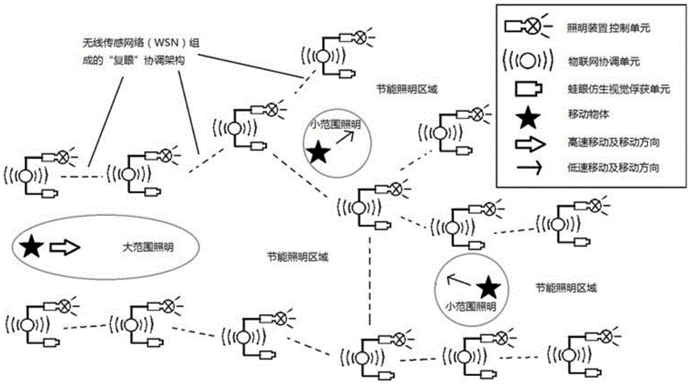
[0035] A lighting system based on visual capture of the Internet of Things, such as figure 1 As shown, it is composed of multiple lighting devices connected, each lighting device includes: frog-eye bionic vision capture unit, IoT coordination unit, lighting device control unit; frog-eye bionic vision capture unit is connected with IoT coordination unit, IoT coordination unit The unit is connected with the lighting device control unit; multiple IoT coordination units are connected through a wireless multi-hop ad hoc network protocol to form an intelligent coordination center.

[0036] The frog-eye bionic vision capture unit adopts an embedded linux or Android platform environment, and forms an intelligent coordination center with other frog-eye bionic vision capture units through the Internet of Things coordination unit connected to it and the intelligent coordina...


PUM


Abstract

The invention belongs to the technical field of dynamic lighting, in particular to a vision capture illuminating system based on the internet of things and a control method of the illuminating system. The vision capture illuminating system is formed by connecting multiple illuminating devices. Each illuminating device comprises a frog eye bionic vision capturing unit, an internet of things coordinating unit and an illuminating device control unit, wherein the frog eye bionic vision capturing unit is connected with the internet of things coordinating unit, and the internet of things coordinating unit is connected with the illuminating device control unit. The multiple internet of things coordinating units are connected through a wireless multi-hop networking protocol, so that an intelligent coordination center is formed. The control method comprises the steps that the size, the movement direction, the movement speed and the acceleration of a moving object in a view field of the system are measured by the capturing units and sent to the internet of things coordinating units, the internet of things coordinating units send corresponding instructions to the control units of all the illuminating devices, in this way, it is guaranteed that dynamic illuminating support effect is achieved in the advancing direction of the moving object, and a sufficient view field range and sufficient light brightness of the illuminating system and the response time in emergency are guaranteed.

Description

technical field [0001] The invention belongs to the technical field of dynamic lighting, and in particular relates to a lighting system based on visual capture of the Internet of Things and a control method thereof. Background technique [0002] Lighting support is a necessary condition for human beings to carry out production and living activities in environments without natural light (such as night, underground facilities). Under the condition that the space for human activities is relatively wide, since the lighting range of a single lighting device is limited, a large number of multiple lighting devices are required to jointly complete the lighting support. However, due to the limited moving speed of human beings (even by means of transportation), only the support of some lighting devices is needed for a period of time, and the lighting support provided by most of the lighting devices in the vast space is wasted. Therefore, driven by the policy of "improving energy util...

Claims


Application Information

Patent Timeline
Patent Type & Authority Patents(China)
IPC IPC(8): H05B37/02
CPCY02B20/40
Inventor 顾思雨杨鸿宇余谦程晓磊李永基庞辉庆
Owner 杨鸿宇
Why Eureka
Try Eureka