Three-dimensional linkage pipe beveling device

A pipeline and linkage technology, used in welding equipment, gas flame welding equipment, metal processing equipment, etc., can solve problems such as re-cutting, and achieve the effect of improving cutting accuracy, improving moving accuracy, and improving angular deflection accuracy.

Inactive Publication Date: 2015-01-07
TIANJIN SHENGJINKANG TECH DEV
View PDF6 Cites 0 Cited by
  • Summary
  • Abstract
  • Description
  • Claims
  • Application Information

AI Technical Summary

Problems solved by technology

It has been found in engineering practice that when the invention is used to obliquely cut the pipe, the pipe port produces a very complicated curved surface, and the angled pipe port cut out by the two-dimensional moving torch cannot meet the requirements of the pipe welding process. Only after secondary treatment can it be used for welding, and some even need to be re-cut

Method used


Image

  • Three-dimensional linkage pipe beveling device
  • Three-dimensional linkage pipe beveling device
  • Three-dimensional linkage pipe beveling device

Examples


Embodiment Construction

[0018] The present invention will be further described below in conjunction with accompanying drawing:

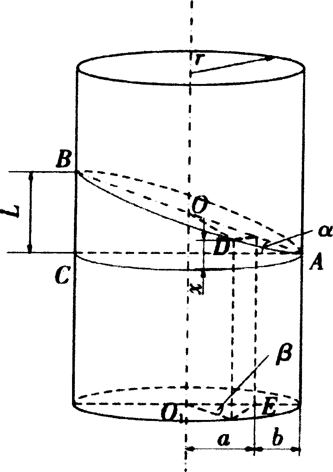
[0019] Such as figure 1 As shown, tgα=L / 2r, cosβ=a / r, a=r·cosβ, b=r-a, x=b·tgα, so a mathematical model tgθ=r / (L / 2-x)=r / [L / 2-L / 2(1-cosβ)]=2r / (Lcosβ)=1 / (tgαcosβ), where r is the radius of the steel pipe, a is the cutting angle, and l is the cutting length. The axial displacement of the cutting torch is x when the cutting torch starts to rotate through the circumferential angle β from point A. It can be seen that the position of the cutting torch at any time is only related to the oblique cutting length of the steel pipe and the central angle of the cutting torch turning along the steel pipe surface , and has nothing to do with the tube radius r.

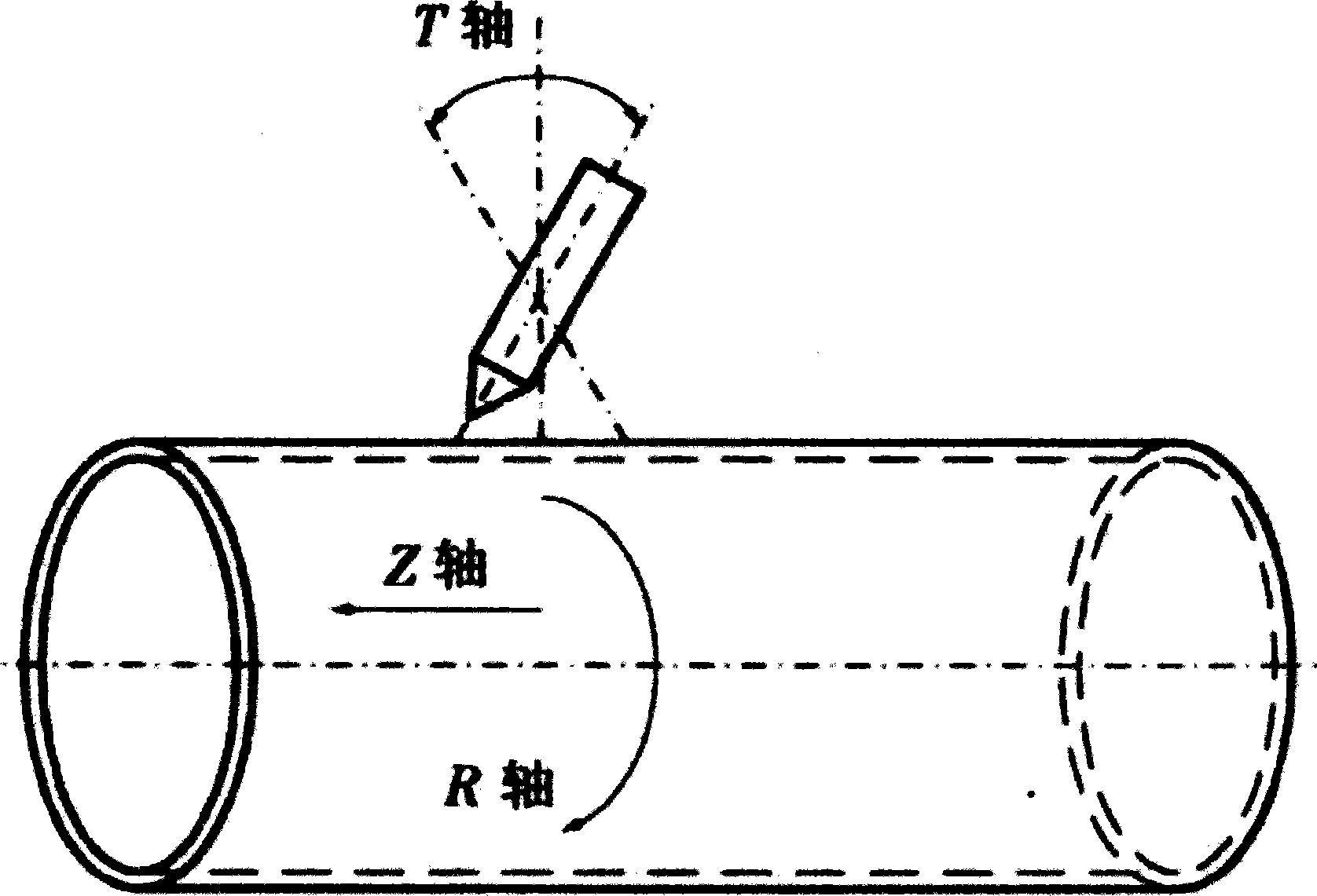
[0020] Such as figure 2 As shown, during the cutting process, the cutting torch has three degrees of freedom. The rotational movement along the circumferential direction of the cut pipe is recorded as the R axis, and the axial...


PUM


Abstract

The invention provides a three-dimensional linkage pipe beveling device, which is used for beveling a pipe so that a pipe end meets the requirement of the pipe on welding process. The three-dimensional linkage pipe beveling device is characterized in that a cutting torch control mechanism is connected with a cutting torch through a cutting torch adjusting mechanism. During cutting, a single chip microcomputer is used for controlling three motors to simultaneously run, axial displacement of the cutting torch is adjusted by a stepping motor A, the angle of the cutting torch is adjusted by a stepping motor B in real time, and the cutting torch is driven by a travelling motor to travel circumferentially along the pipe, so that three-dimensional linkage of the cutting torch is realized. A motion driving angle sensor of each stepping motor transmits signals, the signals together with displacement feedback signals of a displacement sensor are timely transmitted to the single chip microcomputer, follow-up of the two stepping motors is conveniently adjusted, cutting precision is further improved, the problem that a beveled cut surface which is a complex surface cannot be welded is fundamentally solved, one-step forming is realized without trimming, and working efficiency is greatly improved.

Description

technical field [0001] The invention relates to the field of welding and cutting, in particular to a pipe angle cutting device. Background technique [0002] With the development of the national economy, the mileage of oil pipeline and urban pipeline construction is increasing, and the task of pipeline construction is becoming more and more arduous. When long-distance pipelines are docked, due to errors in surveying and construction, deformation of the pipeline itself, and other reasons, the angle of the butt joint of the pipeline often deviates greatly, even far exceeding the standard range (≤3°) stipulated by the state. It is necessary to cut the fixed pipeline at a certain angle (oblique cutting) at the field pipeline construction site. For example, the inventor's patent CN 1803368A "Pipeline Interface Angle Cutting Device", this invention realizes the two-dimensional movement of the cutting torch during the pipe cutting process. It has been found in engineering practic...

Claims


Application Information

Patent Timeline
Patent Type & Authority Patents(China)
IPC IPC(8): B23K7/00B23K7/10
Inventor 刘连增刘星伯玄少娜
Owner TIANJIN SHENGJINKANG TECH DEV
Why Eureka
Try Eureka