Controllable blasting network

A network and control loop technology, applied in blasting and other directions, can solve the problems of harmful effects of blasting, low safety, and high rejection rate of blasting, and achieve the effect of solving low blasting efficiency, saving detonators, and improving safety.

Inactive Publication Date: 2012-07-11
刘国祥
View PDF3 Cites 2 Cited by
  • Summary
  • Abstract
  • Description
  • Claims
  • Application Information

AI Technical Summary

Problems solved by technology

[0003] The purpose of the present invention is to provide a controllable blasting network connection structure to solve the problems of high blasting rejection rate, harmful effects of blasting and low safety in the case of backward blasting equipment and blasting components in our country

Method used


Image

  • Controllable blasting network
  • Controllable blasting network
  • Controllable blasting network

Examples


Embodiment Construction

[0017] In order to facilitate the understanding of the technical solutions of the present invention, the structure and blasting process of the present invention are described in detail below with reference to the accompanying drawings.

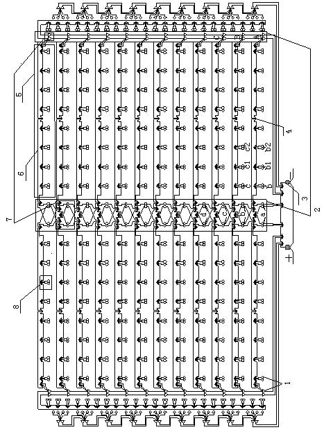
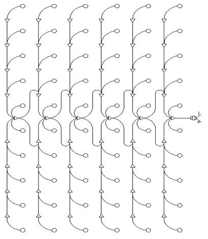
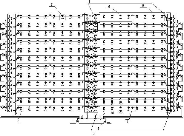
[0018] like figure 1 Shown is an implementation structure of the controllable blasting network of the present invention, wherein 1 is a detonator detonator, and the detonator detonator placed in the hole in the figure is represented by a circle, which is referred to as the detonator in the hole here. Detonator; the detonator detonator placed outside the hole is represented by a triangle, here it is called the detonator detonator outside the hole, and the top of the inverted equilateral triangle indicates the orientation of the detonator's energy gathering point. 2 is a control loop. The control loop is composed of detonating units 7 connected in series. There are two control loops in this embodiment, so there are two detonating units with diff...


PUM


Abstract

The invention discloses a controllable blasting network. The controllable-blasting network comprises nonel detonators, a nonel exciting pen and detonation assemblies, wherein the detonation assemblies are formed by the nonel detonators which are connected in series or in parallel; the plurality of detonation assemblies are connected in series to form a blasting network line; the blasting network is connected on a blasting control loop in parallel to form the controllable blasting network; and the blasting control loop consists of at least one detonation unit connected in series; and the nonel exciting pen is connected with the start end of the blasting control loop. The controllable-blasting network provided by the invention has the advantages that the detonators are saved, the firing rate is high, the operability is strong, and the problems of high misfired rate and low safety under the backward condition of blasting equipment and blasting elements in China are solved.

Description

technical field [0001] The invention belongs to the technical field of civil blasting, and in particular relates to a connection structure capable of accurately controlling the timing sequence of a detonation network. Background technique [0002] Civil blasting engineering is an indispensable industry in metallurgical mines, water conservancy and hydropower, transportation, municipal engineering and other construction fields. However, due to the backward blasting equipment and blasting components in our country, not only the blasting efficiency is low, but also the blasting has a strong harmful effect, often causing personal casualties. Accident, and the detonation tube detonation network technology, the country still does not have a set of blasting network map drawing standards, and there is a lack of communication tools between industries, so the blasting project detonation network is not only simple, but also of a single type, it is difficult to improve the blasting accur...

Claims


Application Information

Patent Timeline
Patent Type & Authority Applications(China)
IPC IPC(8): F42D1/00F42D1/04
Inventor 刘国祥
Owner 刘国祥
Why Eureka
Try Eureka