
Dynamic weighing piezoelectric sensor for vehicle

A piezoelectric sensor and heavy-duty piezoelectric technology, applied in the field of sensors, can solve the problems of long cement curing time, low measurement efficiency, troublesome vehicle traffic, etc., and achieve long-term stability and reliability of weighing accuracy and good consistency of lateral eccentric load. , the effect of high weight measurement efficiency

Active Publication Date: 2012-07-11
郑州衡量科技股份有限公司
View PDF9 Cites 11 Cited by
  • Summary
  • Abstract
  • Description
  • Claims
  • Application Information

AI Technical Summary

Problems solved by technology

[0002] The types of sensors in the existing vehicle weighing system include force conversion type, bridge type, bent plate type, etc. These sensors have a large structure size, and the weighing is aimed at the weight of the entire axle; it usually consists of several tons It is made of steel plate, such a design wastes resources, and in actual installation, there are problems such as large construction volume, long construction period, complicated installation, long cement curing time affecting traffic, etc. In the later use process, there are also problems such as inconvenient drainage and frequent maintenance Moreover, most of the existing sensor weighing, most of the dynamic measurement is much worse than the static measurement accuracy, which brings a lot of trouble to vehicle traffic, low measurement efficiency, and affects traffic.

Method used


Image

  • Dynamic weighing piezoelectric sensor for vehicle
  • Dynamic weighing piezoelectric sensor for vehicle

Examples


Embodiment Construction

[0015] The technical solutions of the present invention will be described in further detail below through specific implementation methods.

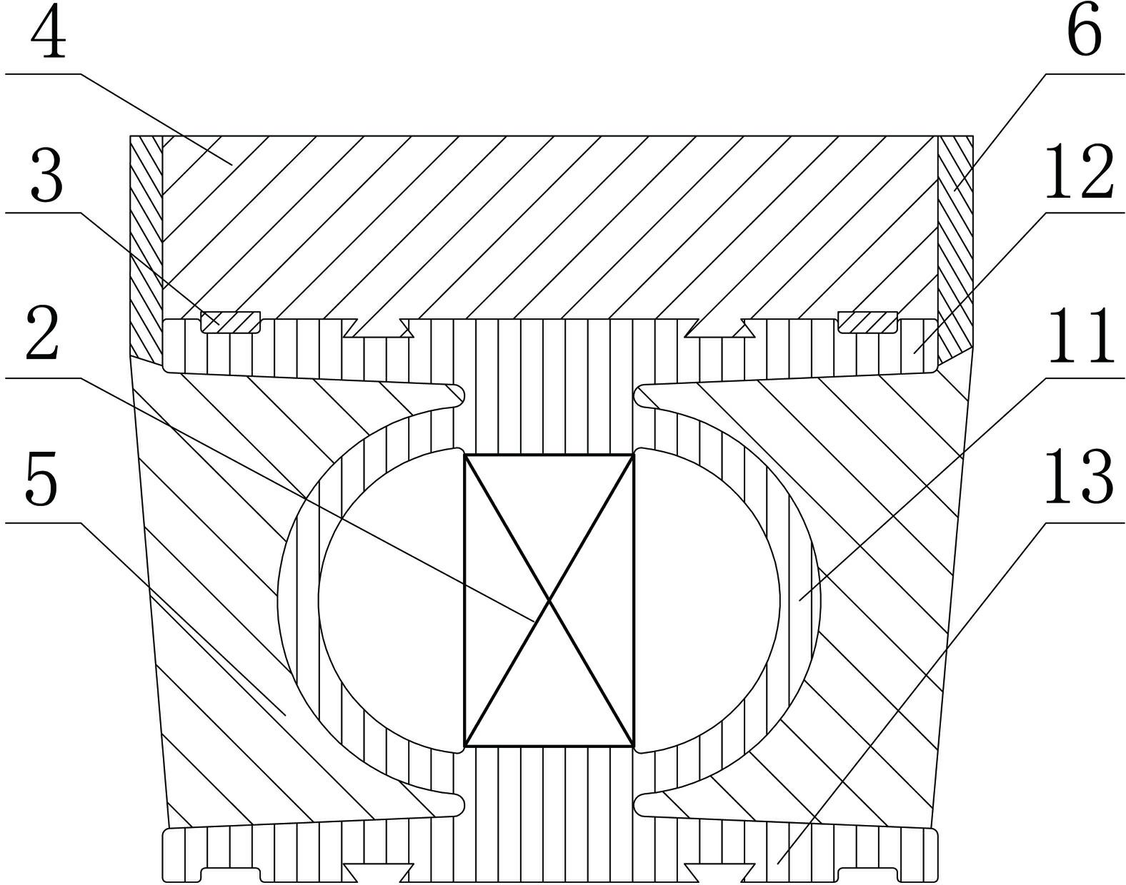
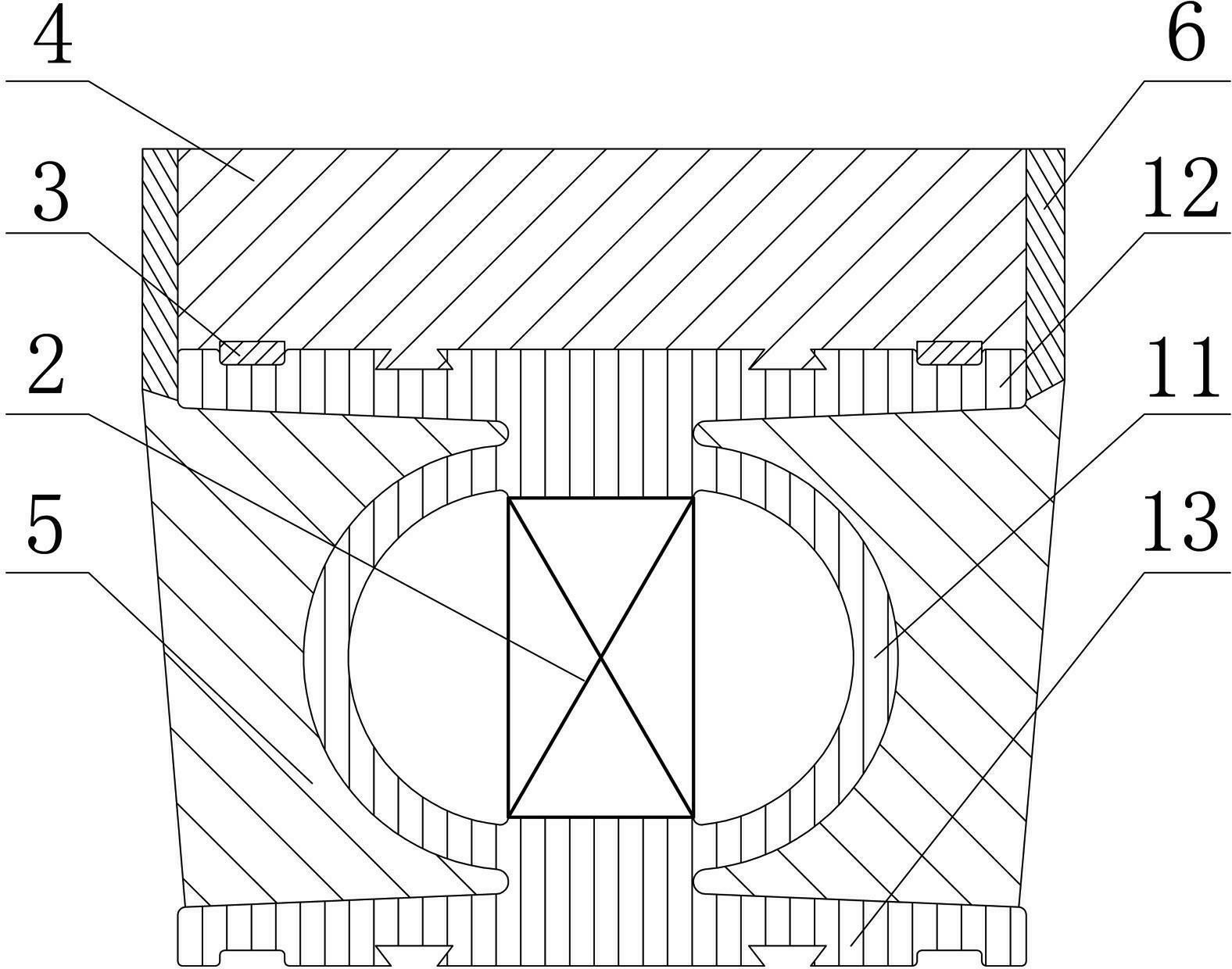
[0016] like figure 1 As shown, a vehicle dynamic weighing piezoelectric sensor, the sensor is in the shape of a strip as a whole, and it includes a strip-shaped road surface force layer 4, a strip-shaped weight-measuring force-bearing profile and a strip-shaped quartz pressure Electric sensor 2.

[0017] The weight-bearing profile includes a force-deformation cavity 11, a weight-bearing top plate 12, and a weight-measuring support base plate 13, wherein the weight-measuring force top plate 12 is arranged parallel to the weight-measuring support base plate 13, The force-deformation cavity 11 is arranged between the weight-measuring force-bearing top plate 12 and the weight-measuring support bottom plate 13, and the centers of the upper and lower outer surfaces of the force-deformation cavity 11 are respectively set on the weight-measuring...


PUM


Abstract

The invention provides a dynamic weighing piezoelectric sensor for a vehicle. The dynamic weighing piezoelectric sensor comprises a weighing stress profile and a quartz piezoelectric sensor; the weighing stress profile comprises a stress deformation cavity, a weighing stress top plate and a weighing supporting bottom plate; the quartz piezoelectric sensor is arranged in the stress deformation cavity; the upper and lower stress surfaces of the quartz piezoelectric sensor are respectively in contact with the upper and lower deformation stress inner cavity surfaces of the stress deformation cavity; the weighing stress top plate is arranged in parallel to the weighing supporting bottom plate; the stress deformation cavity is arranged between the weighing stress top plate and the weighing supporting bottom plate; and the centers of the upper and lower outer cavity surfaces of the stress deformation cavity are respectively arranged in the centers of the weighing stress top plate and the weighing supporting bottom plate. The dynamic weighing piezoelectric sensor for the vehicle has the advantages of scientific design, capability of realizing dynamic measurement, high measurement value precision and high weighing efficiency, and is easy to produce and install.

Description

technical field [0001] The invention relates to a sensor, in particular to a vehicle dynamic weighing piezoelectric sensor. Background technique [0002] The types of sensors in the existing vehicle weighing system include force conversion type, bridge type, bent plate type, etc. These sensors have a large structure size, and the weighing is aimed at the weight of the entire axle; it usually consists of several tons It is made of steel plate, such a design wastes resources, and in actual installation, there are problems such as large construction volume, long construction period, complicated installation, long cement curing time affecting traffic, etc. In the later use process, there are also problems such as inconvenient drainage and frequent maintenance Moreover, most of the existing sensor weighing, most of the dynamic measurement is much worse than the static measurement accuracy, which brings a lot of trouble to vehicle traffic, low measurement efficiency, and affects t...

Claims


Application Information

Patent Timeline
IPC IPC(8): G01G19/03
Inventor 岳正军涂必文
Owner 郑州衡量科技股份有限公司
Learn More