Clamping device, motor, and disk drive device

A technology of clamping device and motor, which is applied in the field of motor, disk drive device and clamping device, and can solve the problem of setting the platform and claw separately with high position accuracy.

Inactive Publication Date: 2012-07-11
NIPPON DENSAN CORP
View PDF5 Cites 0 Cited by
  • Summary
  • Abstract
  • Description
  • Claims
  • Application Information

AI Technical Summary

Problems solved by technology

Therefore, it is difficult to separately adjust the height position of the table portion and the height positions of the plurality of claw portions wit...

Method used


Image

  • Clamping device, motor, and disk drive device
  • Clamping device, motor, and disk drive device
  • Clamping device, motor, and disk drive device

Examples


Embodiment Construction

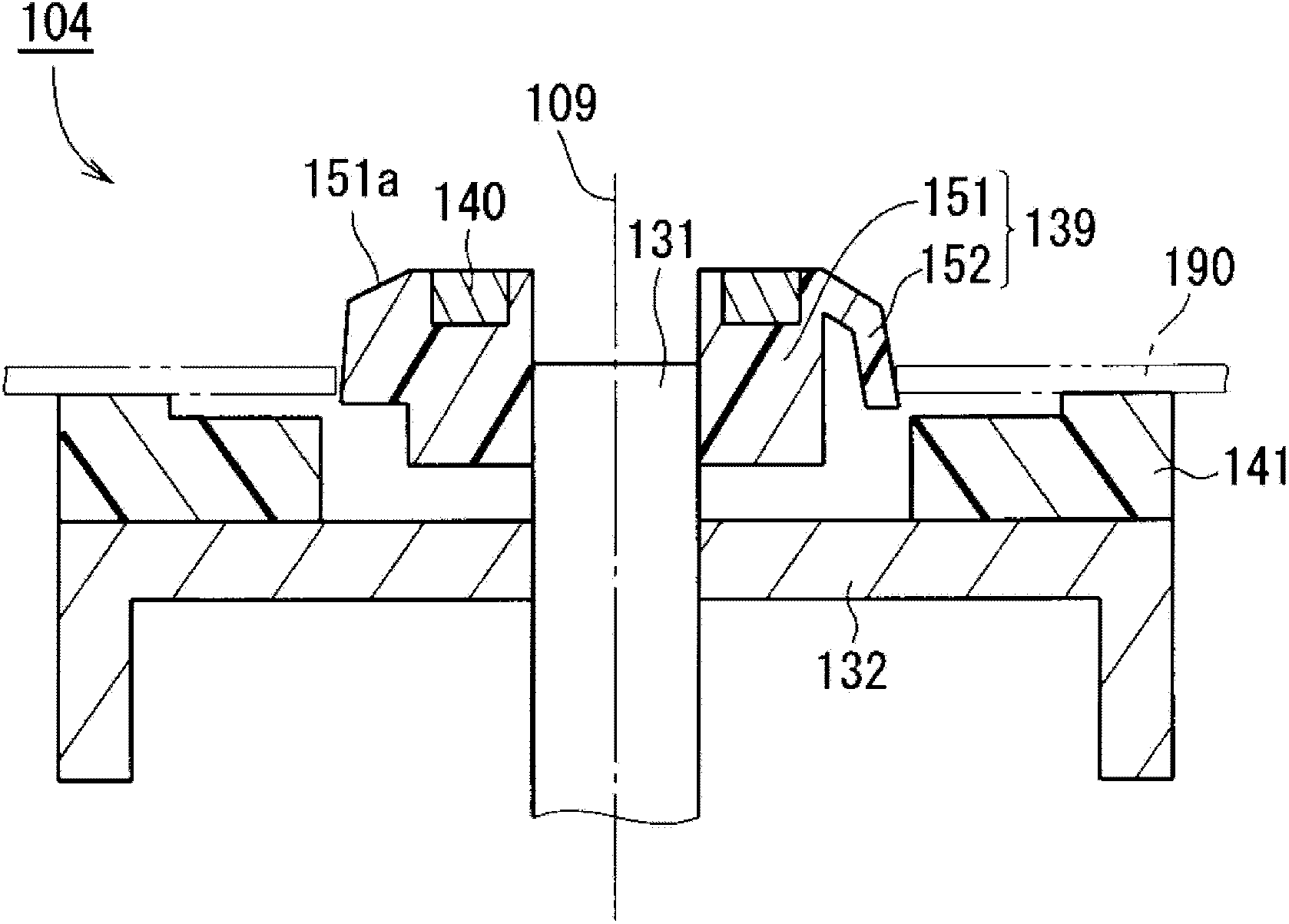
[0058] Hereinafter, exemplary embodiments of the present invention will be described with reference to the drawings. In addition, in the following description, the direction along the central axis of the clamp device is defined as the up-down direction, and the aligning portion side is defined as the upper side with respect to the rotor holder, and the shape and positional relationship of each member will be described. However, this only defines the up and down directions for the convenience of describing the present invention, and does not limit the postures of the motor and the disk drive device of the present invention during use.

[0059] 1. Clamping device according to one embodiment

[0060] figure 1 It is a vertical cross-sectional view of the clamp device 104 according to one embodiment of the present invention. Such as figure 1 As shown, the clamping device 104 includes a shaft 131 , a rotor holder 132 , a disc loading portion 141 , an aligning portion 139 and a co...


PUM


Abstract

The invention provides a clamping device, a motor, and a disk drive device. In the clamping device, a disk loading portion for loading a disk and a self-aligning portion for supporting the inner periphery of the disk are split parts. That is to say, the disk loading portion and the self-aligning portion are not continuous and respectively directly fixed on a shaft or indirectly fixed on the shaft via more than one part. Thus, relative to the surface used as a design reference, the disk loading portion and the self-aligning portion are respectively arranged at high position precision. Compared with the way of fixing a one-piece part comprising the parts like the disk loading portion on a position near to an upper end of the shaft, the load near to the upper end of the shaft is lightened. Thus, the elastic deformation near to the upper end of the shaft is suppressed. Therefore, the vibration and noise of the disk are suppressed during the rotating process.

Description

technical field [0001] The invention relates to a clamping device, a motor, and a disk drive device. Background technique [0002] In a disk drive device such as an optical disk drive, a brushless motor for rotating the disk is arranged. The brushless motor has a clamp that rotates together with the rotating part. The disk drive device holds the disk with a clamp and rotates the disk by driving a brushless motor. [0003] For example, Japanese Laid-Open Publication No. 2008-305460 describes a conventional brushless motor with a clamping device. Japanese Unexamined Patent Publication No. 2008-305460 describes a motor including a rotor yoke and a turntable fixed to a shaft at a position above the rotor yoke. [0004] In Japanese Unexamined Patent Publication No. 2008-305460, the turntable has a table portion on which a disk is mounted, and a plurality of claws that come into contact with the inner peripheral surface of the disk. In addition, the turntable is fixed near the...

Claims


Application Information

Patent Timeline
IPC IPC(8): G11B17/028H02K7/08
Inventor 山根拓也大山诚一
Owner NIPPON DENSAN CORP
Why Eureka
Try Eureka