Magnetic suspension device
A technology of magnetic levitation and levitation, applied in the direction of magnetic attraction or thrust holding device, electrical components, etc., can solve the problems of cost increase, device reliability decrease, excitation current increase, etc.
- Summary
- Abstract
- Description
- Claims
- Application Information
AI Technical Summary
Problems solved by technology
Method used
Image
Examples
Example
[0126] (First embodiment)
[0127] (1) Overall composition
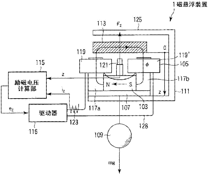
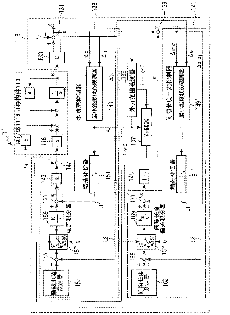
[0128] figure 2 It is a schematic diagram showing the structure of the magnetic levitation device according to the first embodiment, and its overall structure is indicated by 1'.
[0129] The magnetic levitation device 1'has the same structure as the above-mentioned magnetic levitation device 1, and includes a levitation body 111, a guide member 113, a driver 116, a gap sensor 121, a current sensor 123 and an excitation voltage calculation unit 115. Here, the excitation current i detected by the current sensor 123 z Current deviation Δi when the target value is zero z the same.
[0130] In this magnetic levitation device 1', the excitation voltage calculation unit 115 is configured as follows.
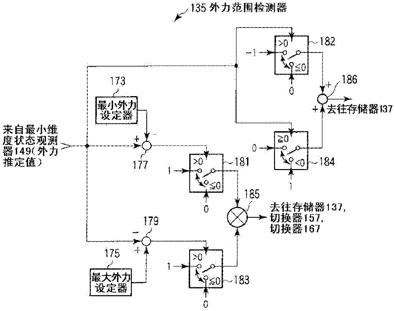
[0131] That is, the excitation voltage calculation unit 115 includes a sensor unit 130, a subtractor 131, a zero power controller 133, an external force range detector 135, a memory 137, a subtractor 139, a gap length constant contro...
Example
[0199] (Second embodiment)
[0200] Next, the second embodiment will be described.
[0201] In the second embodiment, the excitation voltage and excitation current are calculated for each mode of the motion coordinate system of the suspension. Here, a case where the magnetic levitation device of the present invention is applied to an elevator will be described as an example.
[0202] Figure 5 It is a schematic diagram showing the structure of the magnetic levitation device according to the second embodiment. The entire structure when the magnetic levitation device is applied to an elevator is denoted by reference numeral 10. also, Image 6 Is a perspective view showing the structure of the frame portion of the magnetic levitation device, Figure 7 It is a perspective view showing the surrounding structure of the guide unit of the magnetic levitation device, Figure 8 It is a plan view showing the structure of the magnet unit of the magnetic levitation device.
[0203] Such as Figur...
Example
[0314] (Third embodiment)
[0315] Next, the third embodiment will be described.
[0316] In the first and second embodiments, the magnet unit is installed on the side of the suspension, but this does not limit the installation position of the magnet unit, such as Figure 16 As shown, the magnet unit can also be arranged on the ground side. In addition, in order to simplify the description, in the following, the parts common to the first and second embodiments are described with the same reference numerals.
[0317] Figure 16 It is a schematic diagram showing the structure of the magnetic levitation device according to the third embodiment, and its overall structure is indicated by the symbol 300.
[0318] The magnetic levitation device 300 has an auxiliary support part 302, a magnet unit 107, a guide member 304, an anti-vibration table 306, a linear guide 308, an excitation voltage calculation part 115, a power amplifier 313, a gap sensor 121, and a current sensor 123.
[0319] The c...
PUM
 Abstract
Description
Claims
Application Information
 - R&D Engineer
- R&D Manager
- IP Professional
- Industry Leading Data Capabilities
- Powerful AI technology
- Patent DNA Extraction
Browse by: Latest US Patents, China's latest patents, Technical Efficacy Thesaurus, Application Domain, Technology Topic, Popular Technical Reports.
© 2024 PatSnap. All rights reserved.Legal|Privacy policy|Modern Slavery Act Transparency Statement|Sitemap|About US| Contact US: help@patsnap.com


