Commutator motor

A technology of electric motor and commutator, which is applied in the field of iron core composition of commutator motor, can solve the problems such as difficulty in reducing copper loss, improving efficiency, reducing cross-sectional area, etc., and achieves the effect of reducing iron loss and suppressing the increase of excitation current

Inactive Publication Date: 2005-02-16
HITACHI HOME & LIFE SOLUTIONS INC
View PDF0 Cites 1 Cited by
  • Summary
  • Abstract
  • Description
  • Claims
  • Application Information

AI Technical Summary

Problems solved by technology

[0008] However, in a motor whose volume has been reduced to the limit and weight has been reduced, the cross-sectional area of ​​the magnetic flux flow path is generally reduced. Therefore, it is difficult to reduce the copper loss by making up for the increase in the current with the magnetic fl

Method used


Image

  • Commutator motor
  • Commutator motor
  • Commutator motor

Examples


Example Embodiment

[0022] Hereinafter, an example of the embodiment of the present invention will be described based on FIGS. 1 to 6.

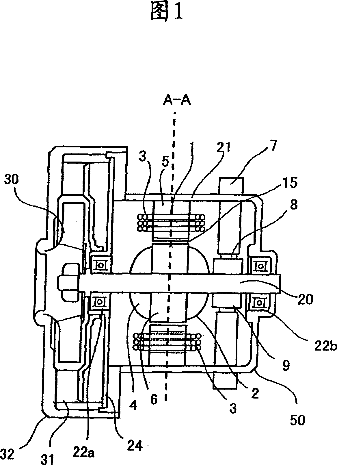
[0023] Fig. 1 shows an embodiment of the structure of the electric blower of the present invention. The motor side of the electric blower 50 is composed of the armature 2 and the stator 1 in the housing 21 and the end bracket 24. In addition, a diffuser 31 and a housing 32 are provided to surround the fan 30 provided at the end of the output shaft of the motor.

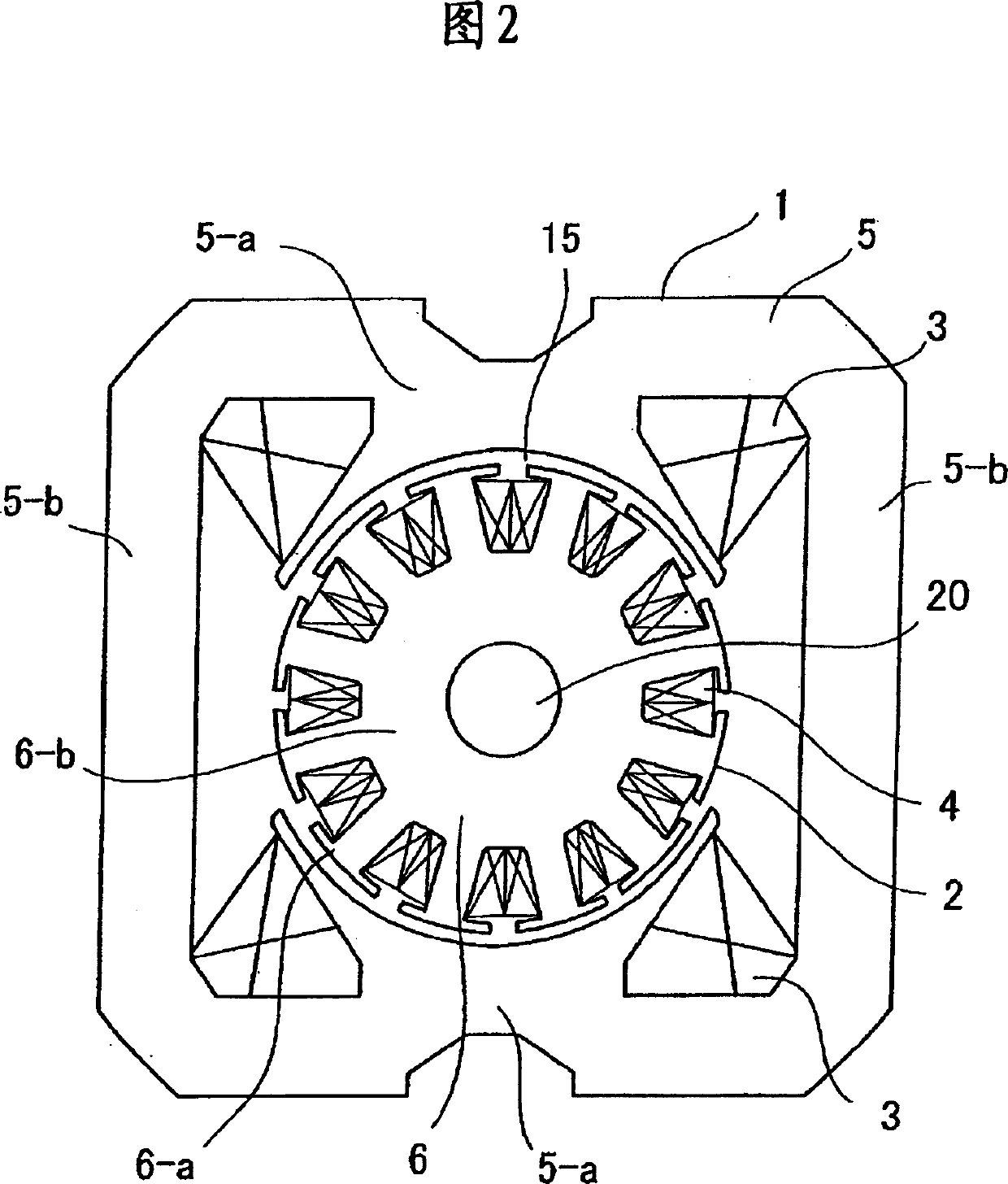
[0024] The stator 1 of the electric motor is composed of a stator core 5 and a field coil 3 in a housing 21, and a main magnetic flux is generated by the field magnetomotive force by passing a current through the field coil 3. The armature 2 arranged with a gap 15 from the stator core 5 has a shaft 20 supported by bearings 22a and 22b provided on the shaft of the housing 21 and the end bracket 24. The shaft 20 is provided with a commutator 9 and an armature core 6. The armature coil 4 is wound around the sl...


PUM


Abstract

The commutator motor includes a stator core made of a material reduced in the deterioration of magnetic characteristics even in a high flux density region (about 1.6-1.8T), and the armature core made of a material reduced in deterioration to an at least inside flux density region (about 1.2-1.4T) and good in iron loss characteristics, and is constituted by combining both. To obtain a high efficiency commutator motor suppressing an exciting current increase while performing the iron loss reduction of an armature core of the commutator motor carried in a vacuum cleaner.

Description

Technical field [0001] The present invention relates to a core structure of a commutator motor (commutator motor) used in an electric blower such as an electric vacuum cleaner. Background technique [0002] In the past, in motors used for electric blowers, commutator motors with two poles were often used. This is because the motor can have series excitation characteristics, that is, the rotation speed increases when the load is light, and the rotation speed decreases when the load is heavy, and high torque is generated, so it has characteristics suitable for driving a blower. [0003] In the conventional commutator motor, the stator core and the armature core are made of the same material. Electromagnetic steel sheets are punched out of a metal die and laminated to form the stator and armature cores. The excitation coil is wound on the magnetic poles of the stator core. The armature coil is wound in the groove of the armature core. Here, the electric vacuum cleaner is one of the ...

Claims


Application Information

Patent Timeline
IPC IPC(8): A47L9/00H02K1/02H02K1/06H02K1/12H02K1/18H02K1/22H02K23/00H02K23/40
Inventor 常乐文夫三上浩幸谷口司原田秀行金贺靖
Owner HITACHI HOME & LIFE SOLUTIONS INC
Why Eureka
Try Eureka