Pressure fuselage of an aircraft with aft-side pressure bulkhead

A pressure chamber and fuselage technology, applied in the direction of fuselage bulkhead, fuselage, aircraft parts, etc., can solve the problem of troublesome removal of debris, reduce work cost and ensure static stability.

Inactive Publication Date: 2015-09-09
AIRBUS OPERATIONS GMBH
View PDF6 Cites 0 Cited by
  • Summary
  • Abstract
  • Description
  • Claims
  • Application Information

AI Technical Summary

Problems solved by technology

In addition, when drilling the riveting holes on both sides of the pressure bulkhead, there are chips that need to be removed rather cumbersomely

Method used


Image

  • Pressure fuselage of an aircraft with aft-side pressure bulkhead
  • Pressure fuselage of an aircraft with aft-side pressure bulkhead
  • Pressure fuselage of an aircraft with aft-side pressure bulkhead

Examples


Embodiment Construction

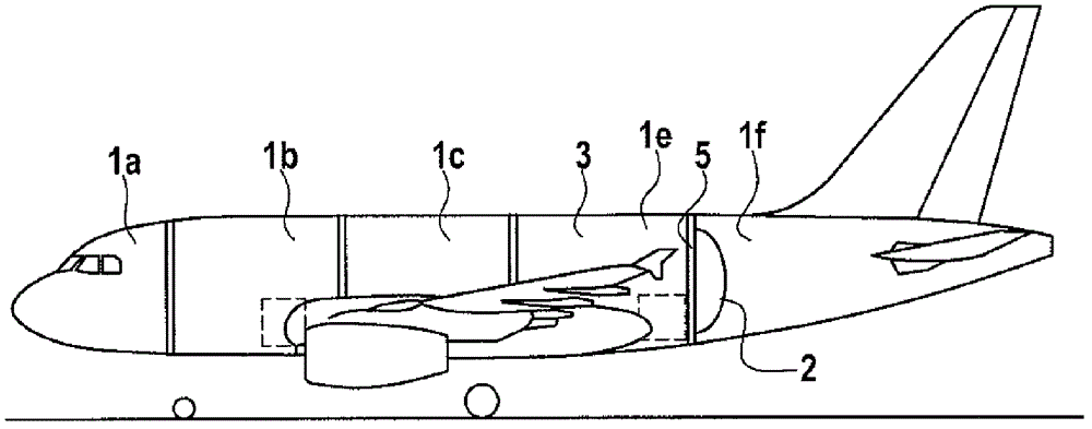
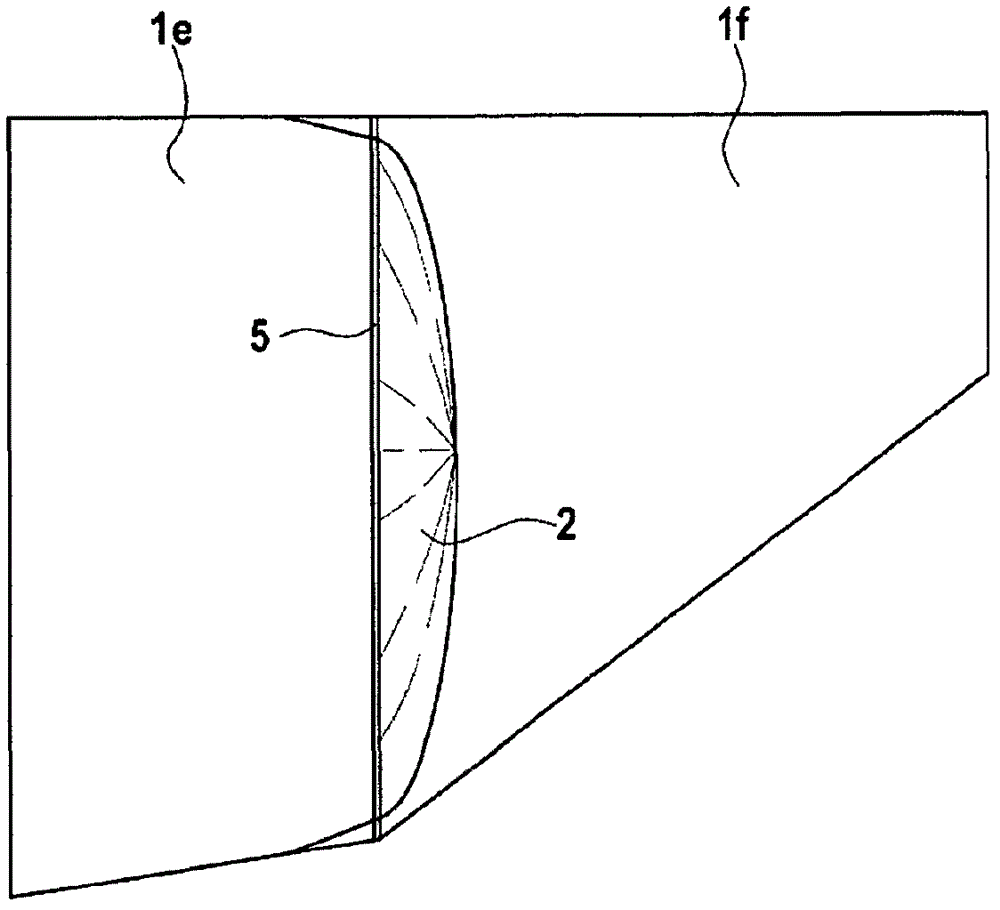
[0028] according to figure 1 , viewed in the longitudinal direction, the pressure fuselage of the aircraft consists of a plurality of fuselage sections 1a-1e, which are connected to each other at the borders by closed elliptical annular cross-sections in order to produce a long-shaped pressure fuselage. Between the fuselage section 1f forming the tail area and the adjacent fuselage section 1e, the tail-side pressure bulkhead 2 is fixed by means of a special bulkhead profile 5, said pressure bulkhead enclosing the pressure area inside the aircraft. 3 Separate from the unpressurized tail region, the pressure bulkhead is assigned to the fuselage section 1f. In the pressurized area 3 inside the aircraft there is a passenger cabin as well as a cargo space arranged below the passenger cabin.

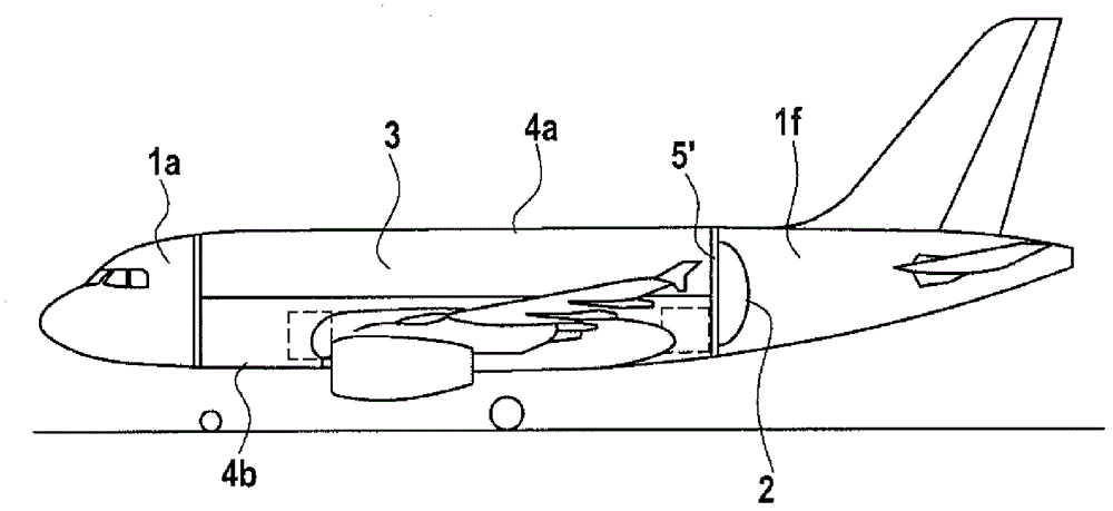
[0029] In contrast, figure 2 A pressure nacelle constructed according to the so-called shell division concept is shown schematically. In addition to the traditional fuselage section 1 a fo...


PUM


Abstract

A pressure fuselage of an aircraft, which fuselage in longitudinal direction comprises several fuselage sections, wherein at least one rear dome-shaped pressure bulkhead is provided to form an aircraft-internal pressurized region, with a ring-shaped frame element profile being provided for radially outward attachment of said dome-shaped pressure bulkhead to at least one fuselage section, wherein the frame element profile on the side of the dome-shaped pressure bulkhead comprises a U-shaped profile section whose first end-side limb is attached towards the back on the dome-shaped pressure bulkhead by way of connecting means, and whose elongated radially outward extending second limb establishes a connection to the at least one fuselage section in such a manner that it is possible for the connecting means to be installed solely from the aircraft-internal pressurized region.

Description

technical field [0001] The invention relates to a pressure fuselage of an aircraft, which is composed in the longitudinal direction of a plurality of fuselage sections, in which at least one tail-side pressure bulkhead is provided for forming a pressure zone inside the aircraft , for the radially outer fastening of the pressure bulkhead to at least one fuselage section, an annular frame profile is provided. Background technique [0002] The field of application of the invention extends in particular to civil aircraft technology. For the transport of people and cargo, civil aircraft with large-volume fuselages that can be divided in several planes are generally used. Therefore, in addition to the wrap-around fuselage construction, there is also a fuselage construction associated with the so-called shell division concept. The fuselage of the latter aircraft forms a force-bearing structure. Furthermore, in the fuselage shell, longitudinally acting forces and torsional forces...

Claims


Application Information

Patent Timeline
Patent Type & Authority Patents(China)
IPC IPC(8): B64C1/10
CPCB64C1/068B64C1/10B64C1/061
Inventor 吉汉吉尔·萨利勒甘马丁·贝克曼
Owner AIRBUS OPERATIONS GMBH
Why Eureka
Try Eureka