
Workpiece clamping head structure

A technology of workpiece clamping and tightening head, which is applied in the direction of workpiece clamping devices and manufacturing tools, which can solve the problems of difficult control of clamping force and unstable clamping of clamping devices, and achieve convenient and accurate clamping force and reliable installation. clip effect

Inactive Publication Date: 2012-07-18
无锡舒比德自动化科技有限公司
View PDF0 Cites 1 Cited by
  • Summary
  • Abstract
  • Description
  • Claims
  • Application Information

AI Technical Summary

Problems solved by technology

[0002] When the workpiece is to be processed on the communication box, the workpiece must be fixed and clamped. During the process of fixing and clamping the workpiece, the common clamping method is to move the piston rod of the cylinder to push the workpiece clamping head to clamp the workpiece. The clamping of the clamping device is unstable, and the clamping force is not easy to control

Method used


Image

  • Workpiece clamping head structure
  • Workpiece clamping head structure

Examples


Embodiment Construction

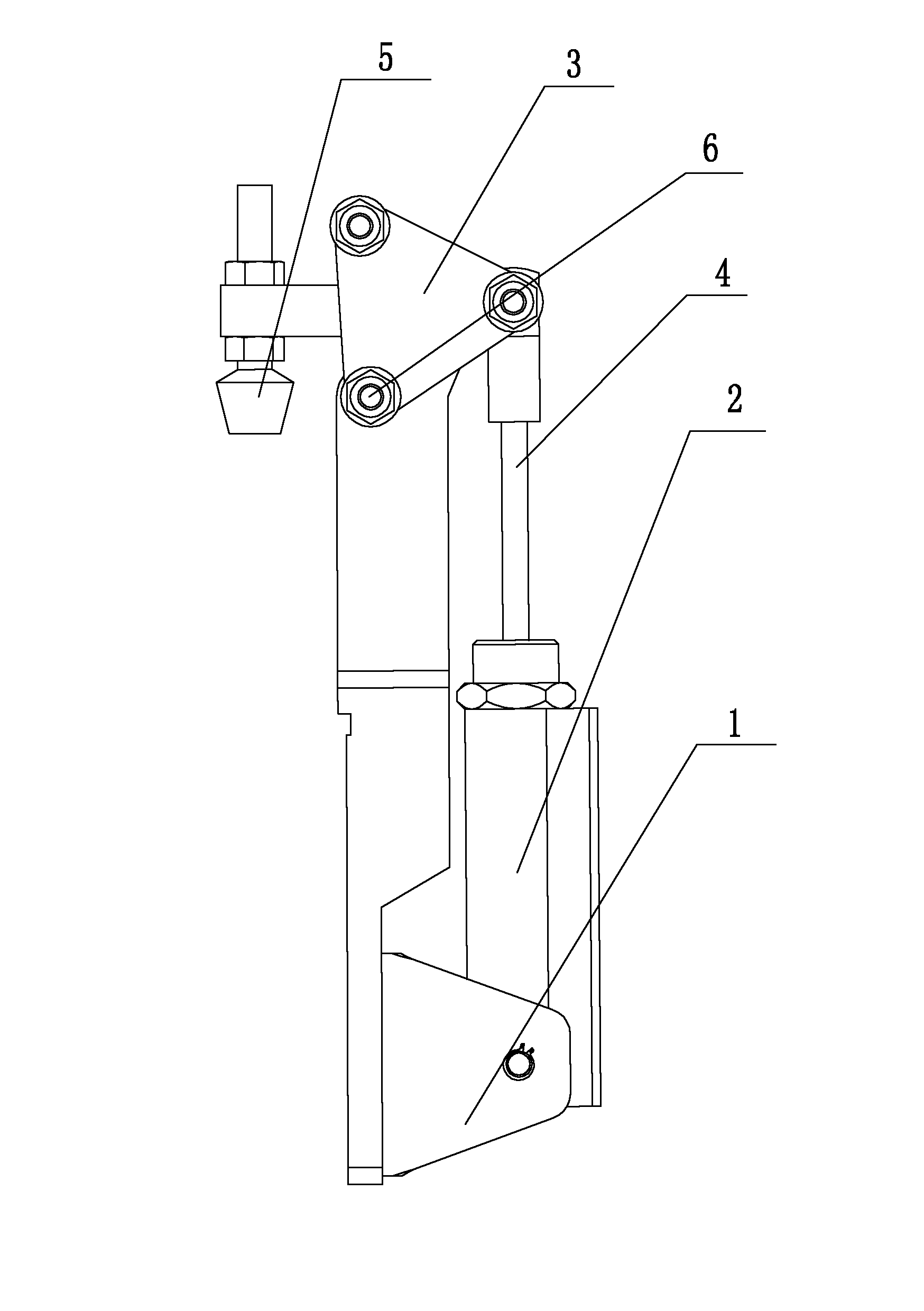
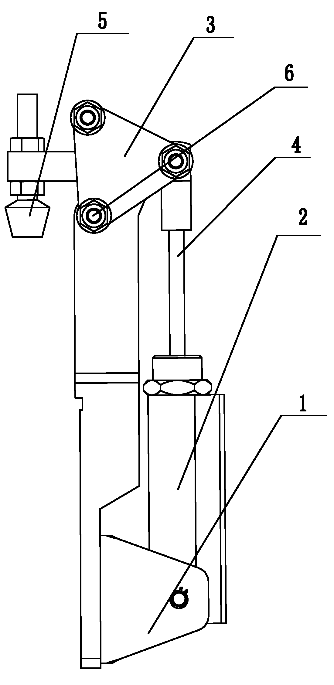
[0008] See figure 1 , a workpiece clamping head structure, which includes a support base 1, a clamping cylinder 2 is fixed on the support base 1, one corner of the triangular lever connecting rod 3 is hinged on the supporting base 1, and the other corner of the triangular lever connecting rod 3 The piston rod 4 of the clamping cylinder is hingedly connected, and a rubber clamping block 5 is fixed on one end of the triangular lever connecting rod 3. When the cylinder is working, the cylinder piston rod 4 telescopically drives the triangular lever connecting rod 3 to rotate around the hinge 6, driving the rubber clamping block. The block 5 moves up and down, realizing the clamping of the workpiece by the rubber clamping block 5 .

[0009] In this embodiment, a triangular lever connecting rod is used. Of course, different shapes of the lever connecting rod can also be used. As long as the principle of leverage is adopted, the two ends of the lever connecting rod move relatively a...


PUM


Abstract

The invention provides a workpiece clamping head structure capable of stably and reliably clamping a workpiece, and the clamping force is easy to control, the workpiece clamping head structure is characterized in that the workpiece clamping head structure comprises a supporting seat, a clamping cylinder is fixed on the supporting seat, a lever connecting rod is hinged on the supporting seat, one end of the lever connecting rod is connected with a piston rod of the clamping cylinder, and a clamping block is fixed at the other end of the lever connecting rod.

Description

technical field [0001] The invention relates to the field of manufacturing core components of communication technology, in particular to a workpiece clamping head structure. Background technique [0002] When the workpiece is to be processed on the communication box, the workpiece must be fixed and clamped. During the process of fixing and clamping the workpiece, the common clamping method is to move the piston rod of the cylinder to push the workpiece clamping head to clamp the workpiece. The clamping of the clamping device is unstable, and the clamping force is not easy to control. Contents of the invention [0003] In view of the above problems, the present invention provides a workpiece clamping head structure, which can clamp the workpiece stably and reliably, and the clamping force is easy to control. [0004] Its technical solution is as follows, a workpiece clamping head structure, which is characterized in that it includes a support seat, the clamping cylinder is...

Claims


Application Information

Patent Timeline
Patent Type & Authority Applications(China)
IPC IPC(8): B25B11/00
Inventor 高青龙河本精次张洪献
Owner 无锡舒比德自动化科技有限公司
Learn More