Indoor metal ceiling with independently removable face boards

An independent panel and independent surface technology, applied in the direction of ceilings, building components, buildings, etc., can solve the problems of damage to the surface of decorative panels, inability to achieve, not having a simple structure, etc., to solve the requirements of simple structure and low cost, and the overall structure Simple, uniquely designed and ingenious effects

Inactive Publication Date: 2012-07-18
上海克拉美空调有限公司
View PDF5 Cites 21 Cited by
  • Summary
  • Abstract
  • Description
  • Claims
  • Application Information

AI Technical Summary

Problems solved by technology

However, the technical disadvantage of this technology is that each panel is in contact with each other. If it is necessary to overhaul the electrical equipment above the ceiling or replace a single panel, any panel cannot be disassembled separately. operate
It clearly shows that it cannot meet the technical requirement that the panels can be removed independently by simply applying a push force
The indoor ceiling and panel in the prior art can be disassembled by

Method used


Image

  • Indoor metal ceiling with independently removable face boards
  • Indoor metal ceiling with independently removable face boards
  • Indoor metal ceiling with independently removable face boards

Examples


Embodiment 1

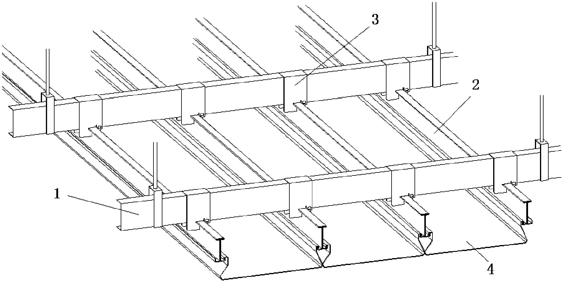
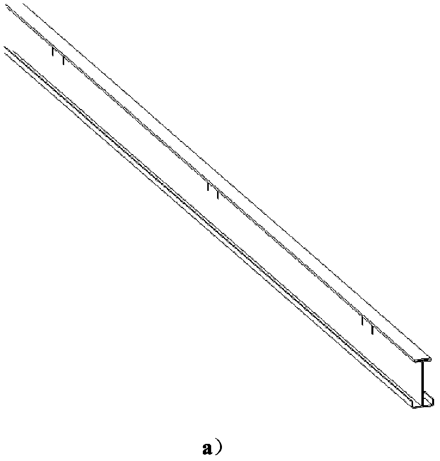
[0033] Such as Figure 1-Figure 3 As shown, this embodiment is composed of vertical and horizontal keel frames and independent panels 4, wherein: the vertical and horizontal keel frames are longitudinal keels 1 and horizontal keels 2 that are perpendicular to each other and movably connected by U-shaped buckles 3, and the longitudinal keels 1 are fixed and suspended on the The ceiling of the building.

[0034] Such as figure 1 with Figure 4 As shown, the U-shaped buckle 3 is sleeved on the longitudinal keel 1 and the inner width of the U-shaped buckle 3 is the same as the outer width of the longitudinal keel 1 .

[0035] Such as Figure 4 As shown in b, the U-shaped buckle 3 is inserted on the transverse keel 2 through the guide groove 9, and the transverse keel 2 is provided with several pairs of insertion slots 8, and the width between each two insertion slots 8 is the same as that of the U-shaped The width x of the buckles 3 is the same, so that the vertical and horizo...

Embodiment 2

[0047] Such as Figure 5b , Image 6 a and Image 6As shown in b, the section of the independent panel 4 adopts an asymmetric trapezoidal structure, and the angles between the two sides of the trapezoidal structure, that is, the first side 5 and the second side 6 and the horizontal plane are α and β respectively, and the first A first polygonal chamfer and a second polygonal chamfer are respectively provided between the side 5 and the second side 6 and the bottom surface, and the two inner angles of the first polygonal chamfer are respectively 180°-α and 93° , the two internal angles of the second polygonal chamfer are 180°-β and 104° respectively; α can be selected from 30-50°, and β can be selected from 40-60°

[0048] Such as Figure 5b As shown, the asymmetric trapezoidal structure makes the bottoms of two adjacent independent panels on the same horizontal plane during installation, and partially overlaps each other in the oblique direction, and realizes a seamless desi...


PUM


Abstract

An indoor metal ceiling with independently removable face boards belongs to the technical field of building engineering and comprises longitudinal keels, transverse keels and independent face boards. The longitudinal keels and the transverse keels are perpendicular to each other and movably connected through U-shaped fasteners, the longitudinal keels are fixedly suspended a ceiling of a building, the cross section of each independent face board is in a nonsymmetrical trapezoidal structure, and a first polygonal chamber and a second polygonal chamber are reserved between two sides and a bottom of each trapezoidal structure respectively. The indoor metal ceiling is especially applicable to large buildings, such as cinemas, conference halls, museums and the like, the single face boards can be removed independently in a simple way, and interior electrical maintenance or construction of the metal ceiling is convenient.

Description

technical field [0001] The invention relates to a metal suspended ceiling in the technical field of construction engineering, in particular to an indoor metal suspended ceiling with independently detachable panels. Background technique [0002] The indoor structures of existing large buildings are generally decorated with alloy ceilings, which not only achieves beauty but also facilitates decoration. However, the panels of most suspended ceiling structures are monolithic structures or fixed structures, and it is often inconvenient to carry out quick disassembly and maintenance when electrical equipment is connected between the suspended ceiling and the ceiling. At the same time, the process from manufacture to assembly of large-scale ceiling panels involves high technological requirements and human resources. If a certain position is damaged, it must be disassembled as a whole to be replaced. Although inspection holes can be preset on the suspended ceiling, as a part of the...

Claims


Application Information

Patent Timeline
IPC IPC(8): E04B9/06E04B9/28
Inventor 季步农康惟宁
Owner 上海克拉美空调有限公司
Why Eureka
Try Eureka