Novel rotational flow impact boiler and manufacturing method thereof

A manufacturing method and boiler technology, which are applied in the combustion method, combustion type, combustion using various fuels, etc., can solve the problems of large NOx emission, inability to take into account the burnout efficiency, and pollution.

Inactive Publication Date: 2014-09-10
北京志源恒通科技有限公司
View PDF6 Cites 0 Cited by
  • Summary
  • Abstract
  • Description
  • Claims
  • Application Information

AI Technical Summary

Problems solved by technology

[0005] The purpose of the present invention is to provide a new type of swirling flow hedging boiler and its manufacturing method, to solve the technical problems of large NOx emissions and serious pollution of the traditional swirling flow hedging boilers that are common on the market now; The technical problem of low burnout efficiency of flow-contrast boilers; it is also necessary to solve the technical problem that the traditional swirl-contrast boilers that are common in the market today cannot balance the low NOx emissions and burnout efficiency

Method used


Image

  • Novel rotational flow impact boiler and manufacturing method thereof
  • Novel rotational flow impact boiler and manufacturing method thereof
  • Novel rotational flow impact boiler and manufacturing method thereof

Examples


Embodiment 1

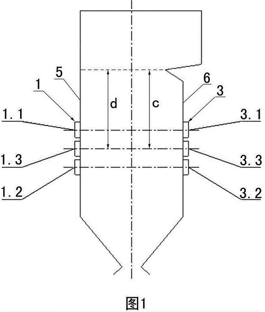
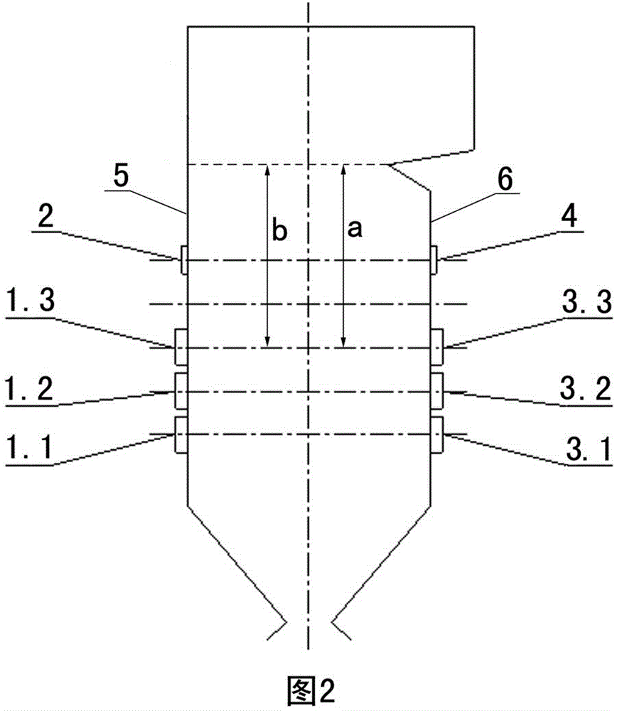
[0036] Embodiment one sees Figure 1-4 , this new type of swirling flow hedge boiler, the front wall 5 of the furnace is provided with three layers of front wall burners 1 and at least one layer of front wall burn-out wind device 2, and the rear wall 6 of the furnace is provided with three layers of rear wall burners 3 and at least one layer of rear wall burn-off air device 4, the distance a from the center line of the uppermost rear wall burner of the new swirl contrast boiler to the bottom of its boiler screen is equal to the rear wall of the traditional swirl contrast boiler of the same size The distance c from the centerline of the burner in the middle layer to the bottom of its boiler panel; the distance b from the centerline of the burner on the uppermost front wall of the new-type swirling flow contrasting boiler to the bottom of its boiler panel is equal to that of a traditional swirling flow contrasting boiler of the same size The distance d from the centerline of the...

Embodiment 2

[0039] Embodiment two see Figure 5 , Figure 7 , Figure 8 , Figure 10 , this new type of swirling flow hedging boiler, the front wall 5 of its furnace is provided with three layers of front wall burners 1 and at least one layer of front wall burn-out wind device 2, and the rear wall 6 of its furnace is provided with two layers of rear wall burners 3 and at least one layer of rear wall burn-out air device 4, the distance a from the centerline of the uppermost rear wall burner in the new swirl contrast boiler to the bottom of the boiler screen is equal to that of a traditional swirl contrast boiler of the same size The distance e from the center line of the burner on the lower layer of the back wall to the bottom of its boiler screen; the distance b from the center line of the burner on the uppermost front wall of the new swirling flow hedge boiler to the bottom of its boiler screen is equal to that of a traditional swirling flow hedge boiler of the same size The distance ...

Embodiment 3

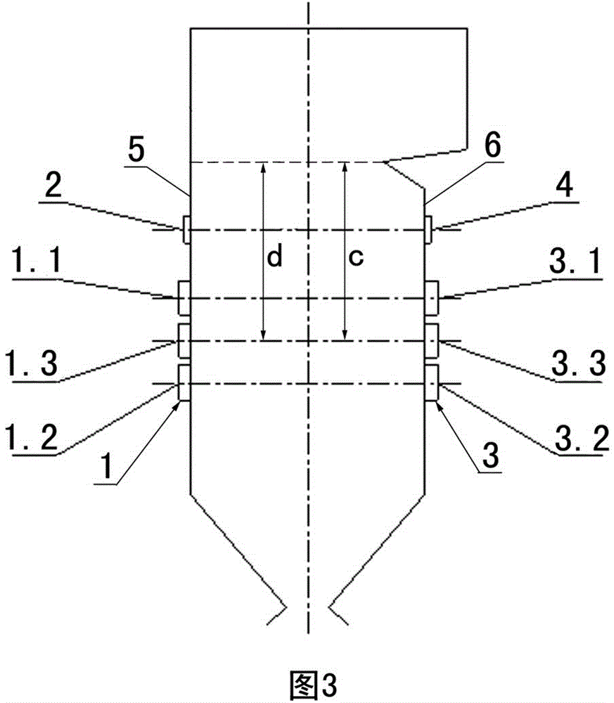
[0042] Embodiment three see Figure 5 , Figure 6 , Figure 8 , Figure 9 , this new type of swirling flow hedging boiler, the front wall 5 of its furnace is provided with three layers of front wall burners 1 and at least one layer of front wall burn-out wind device 2, and the rear wall 6 of its furnace is provided with two layers of rear wall burners 3 and at least one layer of rear wall burn-off air device 4, the distance a from the centerline of the uppermost rear wall burner of the new swirl contrast boiler to the bottom of the boiler panel is equal to the front of the traditional swirl contrast boiler of the same size. The distance d from the centerline of the burner in the middle layer of the wall to the bottom of its boiler panel.

[0043] see Figure 5 , Figure 6 , one of the manufacturing methods of the above-mentioned novel swirling flow contrast boiler, its steps are as follows: Step 1, prepare a traditional swirling flow relief boiler without an overfire air ...


PUM


Abstract

The invention relates to a novel rotational flow impact boiler and a manufacturing method thereof. The distance between the central line of a backwall burner on the uppermost layer of the novel rotational flow impact boiler and the boiler screen bottom is equal to that between the central line of a backwall middle layer burner in the traditional rotational flow impact boiler with the same dimension and the boiler screen bottom; and the distance between the central line of a frontwall burner on the uppermost layer of the novel rotational flow impact boiler and the boiler screen bottom is equal to that between the central line of a frontwall middle layer burner in the traditional rotational flow impact boiler with the same dimension and the boiler screen bottom. The novel rotational flow impact boiler effectively reduces the NOx emission load of the traditional rotational flow impact boiler, and remits and reduces conflict between the NOx emission load and the burn out efficiency. According to the manufacturing method for the novel rotational flow impact boiler, the burn out efficiency of the old traditional rotational flow impact boiler which is used or operates is improved; the NOx emission is reduced, and the effects of the burn out efficiency of the pulverized coal boiler and low NOx emission load are achieved.

Description

technical field [0001] The invention relates to a pulverized coal boiler and a manufacturing method thereof, in particular to a swirling counterflow boiler and a manufacturing method thereof. Background technique [0002] The NOx emitted by the combustion of pulverized coal boilers is one of the most important substances that cause air pollution. The domestic power generation industry has taken coal-fired power plants to control the generation and emission of NOx as one of the important measures to protect the environment. With the increasingly stringent national and local environmental protection policies, the use of various means to reduce NOx emissions from boilers has attracted more and more attention. Advanced low NOx combustion technology can reduce emission concentration to 450-650mg / Nm 3 Below, and with the reduction of boiler NOx emissions, the operating cost of the tail denitrification device will also be reduced. [0003] There are two types of traditional swirl...

Claims


Application Information

Patent Timeline
Patent Type & Authority Patents(China)
IPC IPC(8): F23C5/08
Inventor 赵明羽
Owner 北京志源恒通科技有限公司
Why Eureka
Try Eureka