Method and device for monitoring high-cycle fatigue life of steam turbine integral rotor

A technology of integral forging rotor and high cycle fatigue, which is applied in the field of steam turbines

Active Publication Date: 2014-06-25
SHANGHAI POWER EQUIP RES INST
View PDF2 Cites 1 Cited by
  • Summary
  • Abstract
  • Description
  • Claims
  • Application Information

AI Technical Summary

Problems solved by technology

The existing prediction and monitoring method of steam turbine rotor life, the prediction and monitoring method of low cycle fatigue life of steam turbine integral forged rotor is given, for the prediction of high cycle fatigue life of steam turbine integral There is no suitable method and device available for the monitoring of cycle fatigue life

Method used


Image

  • Method and device for monitoring high-cycle fatigue life of steam turbine integral rotor
  • Method and device for monitoring high-cycle fatigue life of steam turbine integral rotor
  • Method and device for monitoring high-cycle fatigue life of steam turbine integral rotor

Examples


Embodiment 1

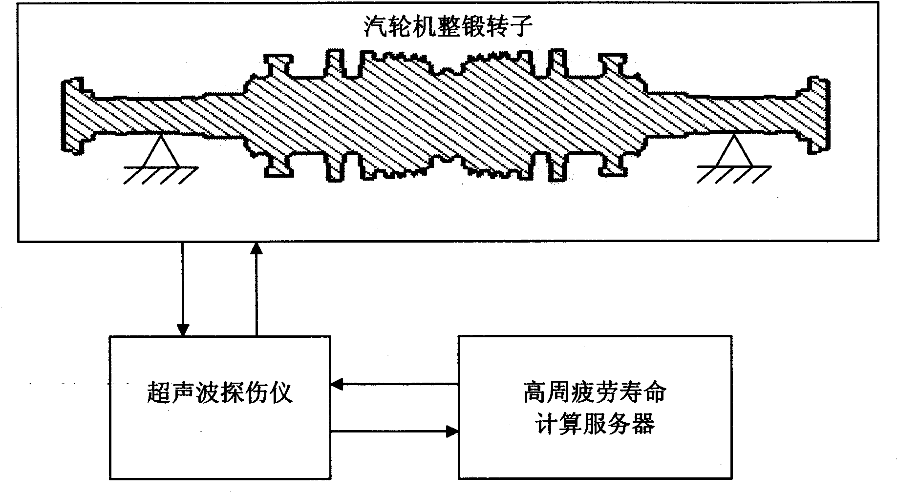
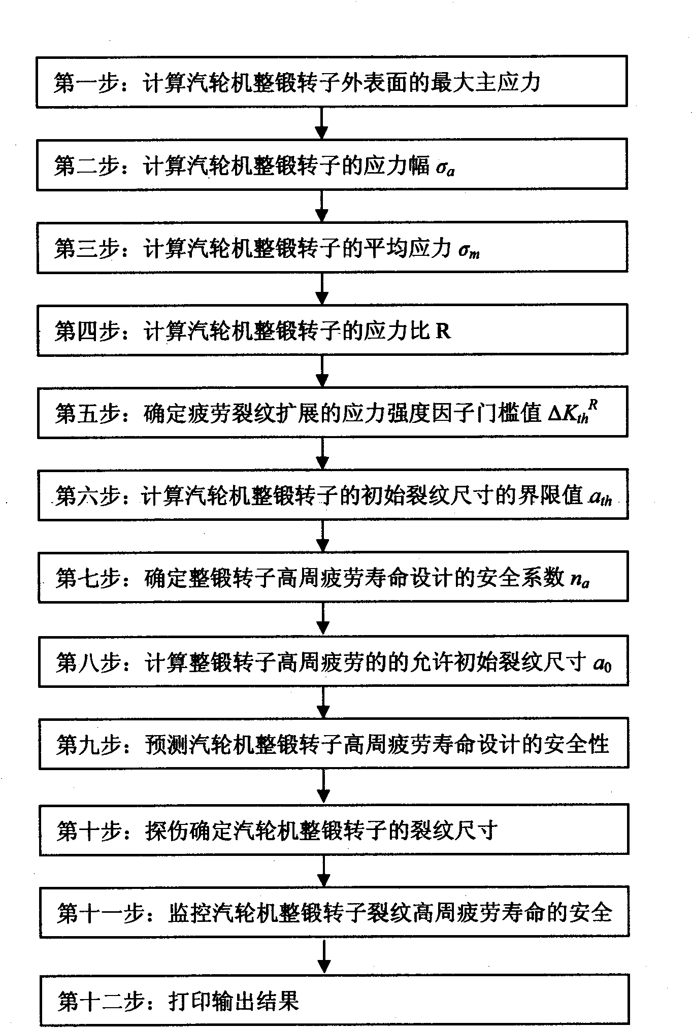
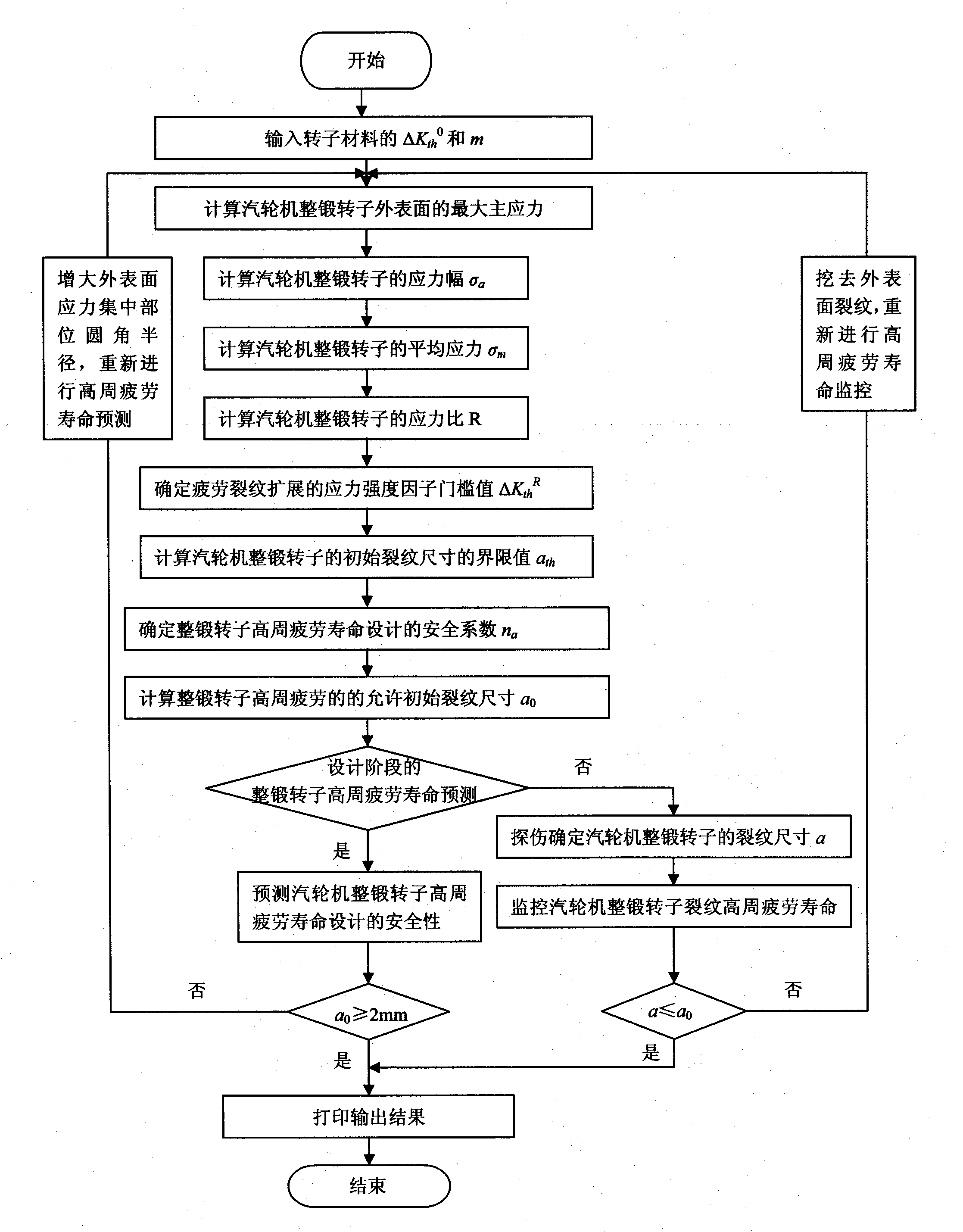
[0065] For a certain type of 600MW thermal power steam turbine, the operating speed is 3000 rpm, and the low-pressure rotor adopts the structure of the integral forged rotor as follows: Figure 4 As shown, the rotor material is 30Cr2Ni4MoV. In the design stage of the whole forged low-pressure rotor of the 600MW thermal power steam turbine, the figure 1 the device shown, figure 2 The flow chart shown and image 3 The computer software shown can calculate the calculation result of the high cycle fatigue life of the whole forged low pressure rotor, and the specific steps are as follows:

[0066] Step 1: Calculate the maximum principal stress on the outer surface of the whole forged rotor of the steam turbine:

[0067] For the steam turbine integral forged rotor, the existing finite element calculation and analysis method is used to calculate the maximum principal stress on the outer surface of the rotor under the steady-state rated load condition. ° position) to determine the...

Embodiment 2

[0116] For a certain type of 600MW thermal power steam turbine, the operating speed is 3000 rpm, and the low-pressure rotor adopts the structure of the integral forged rotor as follows: Figure 4As shown, the rotor material is 30Cr2Ni4MoV. In the manufacturing stage of the whole forged low-pressure rotor of this 600MW thermal power steam turbine, the figure 1 the device shown, figure 2 The flow chart shown and image 3 The computer software shown is used to calculate the monitoring results of the high cycle fatigue life of the whole forged low pressure rotor. The specific steps are:

[0117] The first step to the eighth step: similar to Example 1, the difference is that the outer surface part A of the whole forged low-pressure rotor of the 600MW thermal power steam turbine adopts an optimized and improved design scheme, and the fillet radius of part A is designed to be 300mm. Maximum principal stress σ 1 , projected onto σ 1 The normal stress σ in the direction 1 ′, str...


PUM

PropertyMeasurementUnit
residual stressaaaaaaaaaa

Abstract

The present invention provides a method and device for monitoring high-cycle fatigue life of a steam turbine integral rotor. The device for monitoring the high-cycle fatigue life of the steam turbine integral rotor is characterized by comprising an ultrasonic flaw detector and a compute server, wherein the ultrasonic flow detector is connected with the compute server. The invention has the following advantages: the quantitative prediction and the quantitative monitor of the high-cycle fatigue life of the steam turbine integral rotor are realized; if the safety of the high-cycle fatigue life of the steam turbine integral rotor does not meet the requirements, the steam turbine integral rotor is redesigned during the designing step or a crack on the surface of the steam turbine integral rotor is removed during the manufacturing step, so as to satisfy the safety requirement of the high-cycle fatigue life of the steam turbine integral rotor, furthermore the high-cycle fatigue life of the steam turbine integral rotor is quantitatively predicted and monitored.

Description

technical field [0001] The invention relates to a monitoring method and a monitoring device for the high cycle fatigue life of a whole forged rotor of a steam turbine, belonging to the technical field of steam turbines. Background technique [0002] In the steady-state rated load operation of the steam turbine, due to the action of centrifugal force load and thermal load, the stable static stress in the whole forged rotor of the steam turbine is called the average stress. The static large-span and hundreds of tons steam turbine integral forged rotor, under the action of its own gravity load, generates compressive stress on the outer surface of the entire forged rotor above the center of gravity, and generates tensile stress on the outer surface of the entire forged rotor below the center of gravity. In the operation of the steam turbine, a certain point on the outer surface of the forged rotor, in addition to bearing the stable average stress caused by centrifugal force load...

Claims


Application Information

Patent Timeline
Patent Type & Authority Patents(China)
IPC IPC(8): G01M13/00G01N29/04G01B17/00
Inventor 史进渊杨宇邓志成汪勇江路毅
Owner SHANGHAI POWER EQUIP RES INST
Why Eureka
Try Eureka