Multipole direct-current contactor

A DC contactor and multi-pole technology, applied in the direction of relays, electromagnetic relays, detailed information of electromagnetic relays, etc., can solve the problems of large volume, high power consumption of electromagnetic coils, etc., achieve small volume, compact structure, and solve the problem of excessive volume Effect

Inactive Publication Date: 2014-03-19
SHENYANG 213 CONTROL ELECTRICAL APPLIANCE MFG
View PDF4 Cites 0 Cited by
  • Summary
  • Abstract
  • Description
  • Claims
  • Application Information

AI Technical Summary

Problems solved by technology

[0003] The purpose of the present invention is to provide a multi-pole DC contactor, which solves the problems of the existing technology such as excessive volume and excessive power consumption of electromagnetic coils. It has reasonable design, compact structure, small volume, small contact breaking arc, The contact is safe and reliable, and the rated operating voltage of the DC contactor has been significantly increased to reach the kilovolt level, which meets the requirements of electric buses for public transportation that require low-voltage 24V drive, and also increases the rated operating voltage as required by photovoltaic power generation and wind power generation.

Method used


Image

  • Multipole direct-current contactor
  • Multipole direct-current contactor
  • Multipole direct-current contactor

Examples


Embodiment Construction

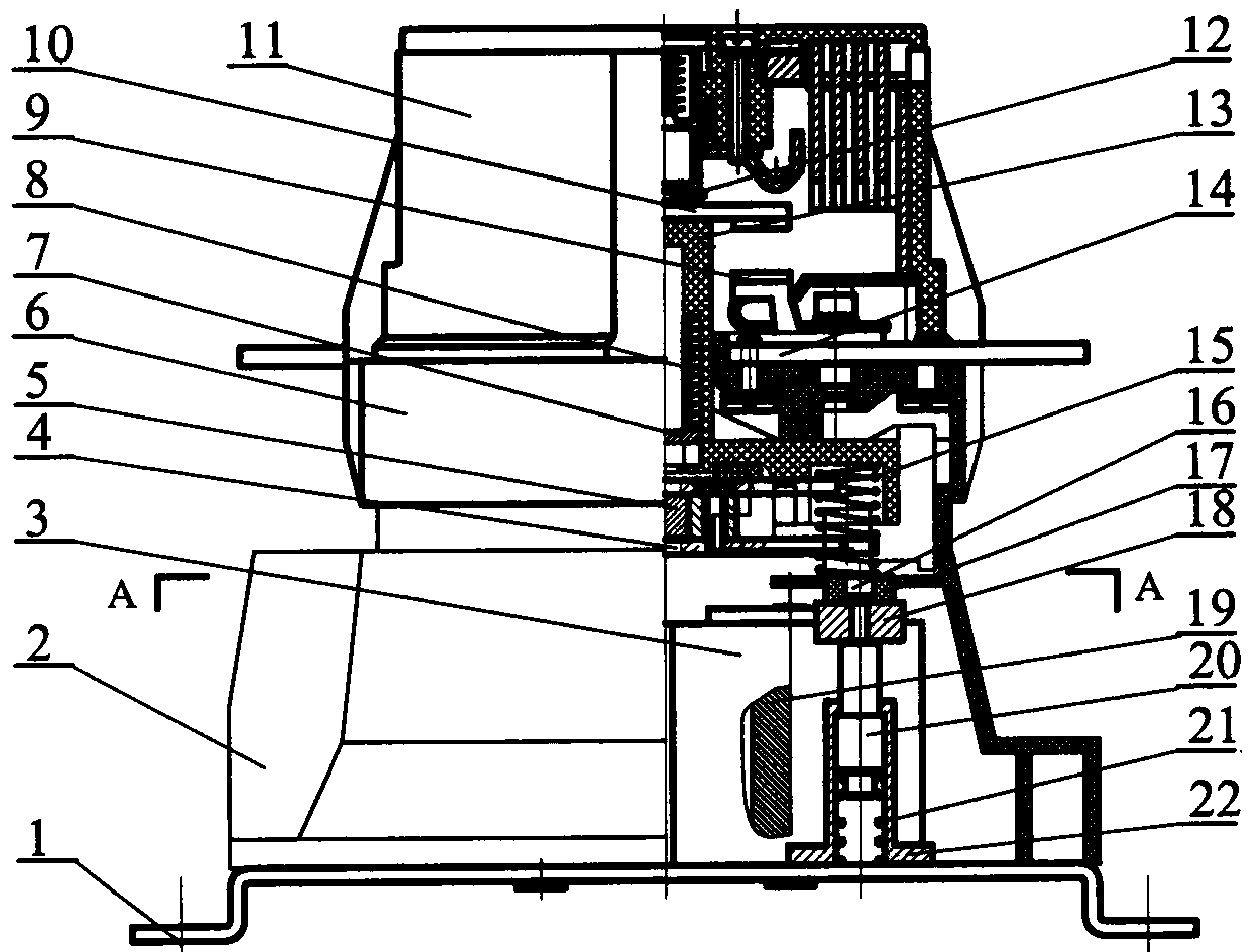
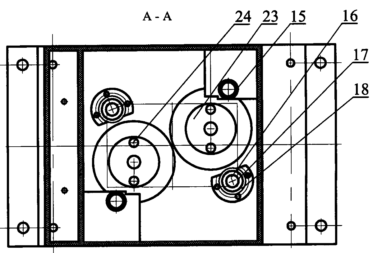
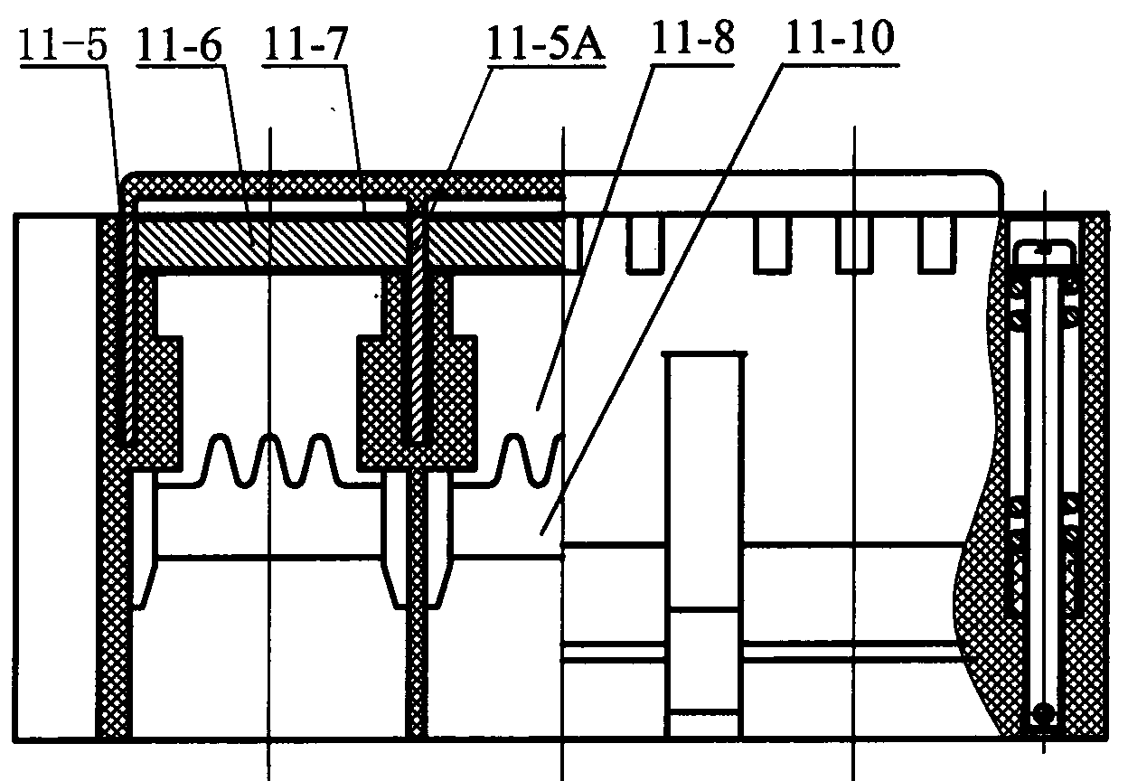
[0014] according to Figure 1~3 The specific structure of the present invention will be described in detail. The multi-pole DC contactor includes three parts: electromagnetic mechanism, arc extinguishing chamber and contact system. The electromagnetic mechanism is mainly composed of a coil 3, an iron core 19, an armature 4, a base plate 1, a booster magnet 18, a magnetic isolation pad 17, a guide rod 20, a spring 21, a guide seat 22, and the like. The arc extinguishing chamber 11 mainly includes a built-in arc extinguishing grid 11-8, an arc strike plate 11-10, a permanent magnet 11-6, a magnetic guide plate 11-5, and a heat insulating sleeve 11-7. The specific structure of the built-in permanent magnet magnetic blowing arc extinguishing structure of the arc extinguishing chamber 11 has been applied for the Chinese patent "DC contactor arc extinguishing device" at the same time. The structure of the arc extinguishing chamber 11 in the drawings of this embodiment is a three-p...


PUM


Abstract

The invention relates to a multipole direct-current contactor which solves the problems of overlarge volume, overmuch electric energy consumption of an electromagnetic coil and the like in the prior art. The multipole direct-current contactor comprises an electromagnetic mechanism, an arc extinguishing chamber and a contact system. The multipole direct-current contactor has the technical points that the electromagnetic mechanism is also provided with a power assisting device which is fixed on a bottom board and mainly consists of a power assisting magnetic block, a copper screw, a magnetism insulating pad, a guide rod, a spring and a guiding seat; magnetic permeating boards or thick magnetic permeating boards are inserted in two side walls of a contact chamber of the arc extinguishing chamber corresponding to electric arc generating positions, a permanent magnet is arranged between the two magnetic permeating boards, wherein the periphery of the permanent magnet is covered by a heat insulating sleeve, so that both ends of the permanent magnet are respectively in seamless adsorption connection with the magnetic permeating boards; and bridge type contacts are fixed on contact supports which support by using contact springs and reaction springs. The multipole direct-current contactor has the advantages of reasonable design, compact structure and small size as well as stable running and safe and reliable contact when the contacts are separated or contacted, and the rated working voltage of the direct-current contactor is obviously improved to a kilovolt level, thereby meeting the requirement on improving the rated working voltages of electric motor coaches for public traffic.

Description

technical field [0001] The invention relates to a switch contactor for a low-voltage electrical appliance, in particular to a multi-pole DC contactor using an arc extinguishing device with a built-in permanent magnet magnetic blowing arc extinguishing structure. It is mainly used in places where the rated working voltage reaches kilovolts, such as electric buses for public transportation, solar energy, and wind energy. Background technique [0002] Existing DC contactors are widely used in electric drive. There are many varieties, but most of them are two normally open contacts. to the conversion circuit control. Generally, the single-pole (1P) interrupter has one contact room, while the two-pole (2P) has two contact rooms, and the four-pole (4P) has four contact rooms. The same contact room is composed of these contact rooms. The interrupter is collectively referred to as the multi-pole interrupter. The traditional DC contactor mainly includes a contact system with a sin...

Claims


Application Information

Patent Timeline
Patent Type & Authority Patents(China)
IPC IPC(8): H01H50/00H01H50/54H01H9/44
Inventor 刘勇白云飞尹显文邸威刘传亭
Owner SHENYANG 213 CONTROL ELECTRICAL APPLIANCE MFG
Why Eureka
Try Eureka