
Vacuum switch, related mechanism, system of vacuum switch and application of vacuum switch

A technology of vacuum switch and switching power supply, which is used in electric switches, high-voltage/high-current switches, high-voltage air circuit breakers, etc. life and other issues, to achieve the effect of no voltage overcharge phenomenon, fast action speed, and reduced opening and closing time

Inactive Publication Date: 2019-10-22
ANHUI HEKAI ELECTRICAL TECH CO LTD
View PDF2 Cites 0 Cited by
  • Summary
  • Abstract
  • Description
  • Claims
  • Application Information

AI Technical Summary

Problems solved by technology

The traditional vacuum switch generally adopts a spring operating mechanism, which has a long opening and closing time, a long pre-breakdown time, a long arc existence time, a large electrical wear on the contact surface, and even causes the contacts to weld and stick, reducing arc extinguishing. Chamber electrical life

Method used


Image

  • Vacuum switch, related mechanism, system of vacuum switch and application of vacuum switch
  • Vacuum switch, related mechanism, system of vacuum switch and application of vacuum switch
  • Vacuum switch, related mechanism, system of vacuum switch and application of vacuum switch

Examples


Embodiment Construction

[0056] Exemplary embodiments of the present disclosure will be described in more detail below with reference to the accompanying drawings. Although exemplary embodiments of the present disclosure are shown in the drawings, it should be understood that the present disclosure may be embodied in various forms and should not be limited by the embodiments set forth herein. Rather, these embodiments are provided for more thorough understanding of the present disclosure and to fully convey the scope of the present disclosure to those skilled in the art.

[0057] Reference will now be made in detail to the exemplary embodiments, examples of which are illustrated in the accompanying drawings. When the following description refers to the accompanying drawings, the same numerals in different drawings refer to the same or similar elements unless otherwise indicated. The implementations described in the following exemplary examples do not represent all implementations consistent with the ...

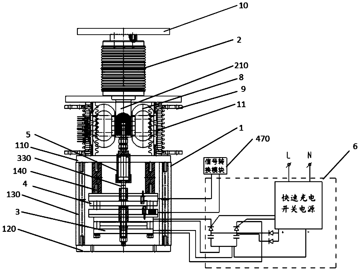
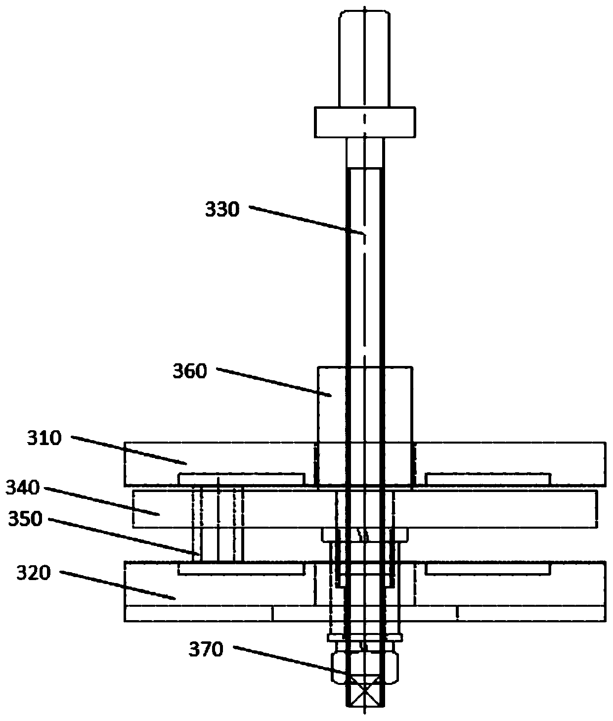
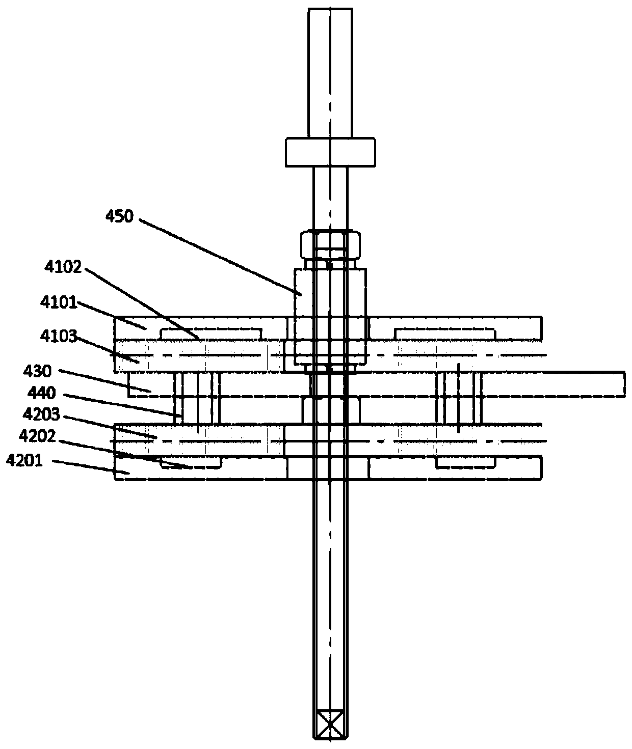

PUM


Abstract

The invention discloses a vacuum switch, a related mechanism, a system of a vacuum switch and application of a vacuum switch. The switch comprises a fast charging switch power supply, a switching-offcapacitor group, a switching-on capacitor group, a diode, a switching-off power electronic switch and a switching-on power electronic switch. The switching-on capacitor group and the switching-off capacitor group are connected with the negative electrode of the fast charging switch power supply, the positive electrodes of the switching-on capacitor group and the switching-off capacitor group are connected with the positive electrode of the fast charging switch power supply through the diode, and the positive electrodes of the switching-on capacitor group and the switching-off capacitor group are respectively connected with the anodes of the switching-on power electronic switch and the switching-off power electronic switch; the cathodes of the switching-on power electronic switch and the switching-off power electronic switch are respectively connected with the incoming line ports of a switching-on coil and a switching-off coil of the vacuum switch, and the negative electrodes of the switching-on capacitor group and the switching-off capacitor group are respectively connected with outgoing line ports of the switching-on coil and the switching-off coil of the vacuum switch; and the pulse output of the fast charging switch power supply is connected with the control electrodes of the switching-on power electronic switch and the switching-off power electronic switch. The problems oflong switching-on and switching-off time and the low speed of the vacuum switch in the prior art are solved.

Description

technical field [0001] The invention relates to a vacuum switch and related mechanisms, systems and applications. Background technique [0002] The vacuum circuit breaker in the prior art has the advantages of small size, light weight, suitable for frequent operation, and no maintenance for arc extinguishing. It is widely used in distribution networks and can be used in industrial and mining enterprises, power plants, and substations. As the protection and control of electrical equipment, it is especially suitable for places that require no oil, less maintenance and frequent operations. The circuit breaker can be configured in central cabinets, double-layer cabinets, and fixed cabinets to control and protect high-voltage electrical equipment. use. The traditional vacuum switch generally adopts a spring operating mechanism, which takes a long time to open and close, a long pre-breakdown time, a long time for the arc to exist, a large electrical wear on the contact surface, a...

Claims


Application Information

Patent Timeline
Patent Type & Authority Applications(China)
IPC IPC(8): H01H33/666
CPCH01H33/666H01H33/66H01H33/664
Inventor 李俭华余振
Owner ANHUI HEKAI ELECTRICAL TECH CO LTD
Learn More