Vacuum cup capable of cooling and heating instantly
A thermos cup and rapid heating technology, applied in the field of thermos cups, can solve the problems of inconvenient use of thermos cups, inability to steplessly adjust air cooling or air heating speed, and difficulty in popularization and application.
- Summary
- Abstract
- Description
- Claims
- Application Information
AI Technical Summary
Problems solved by technology
Method used
Image
Examples
Embodiment 1
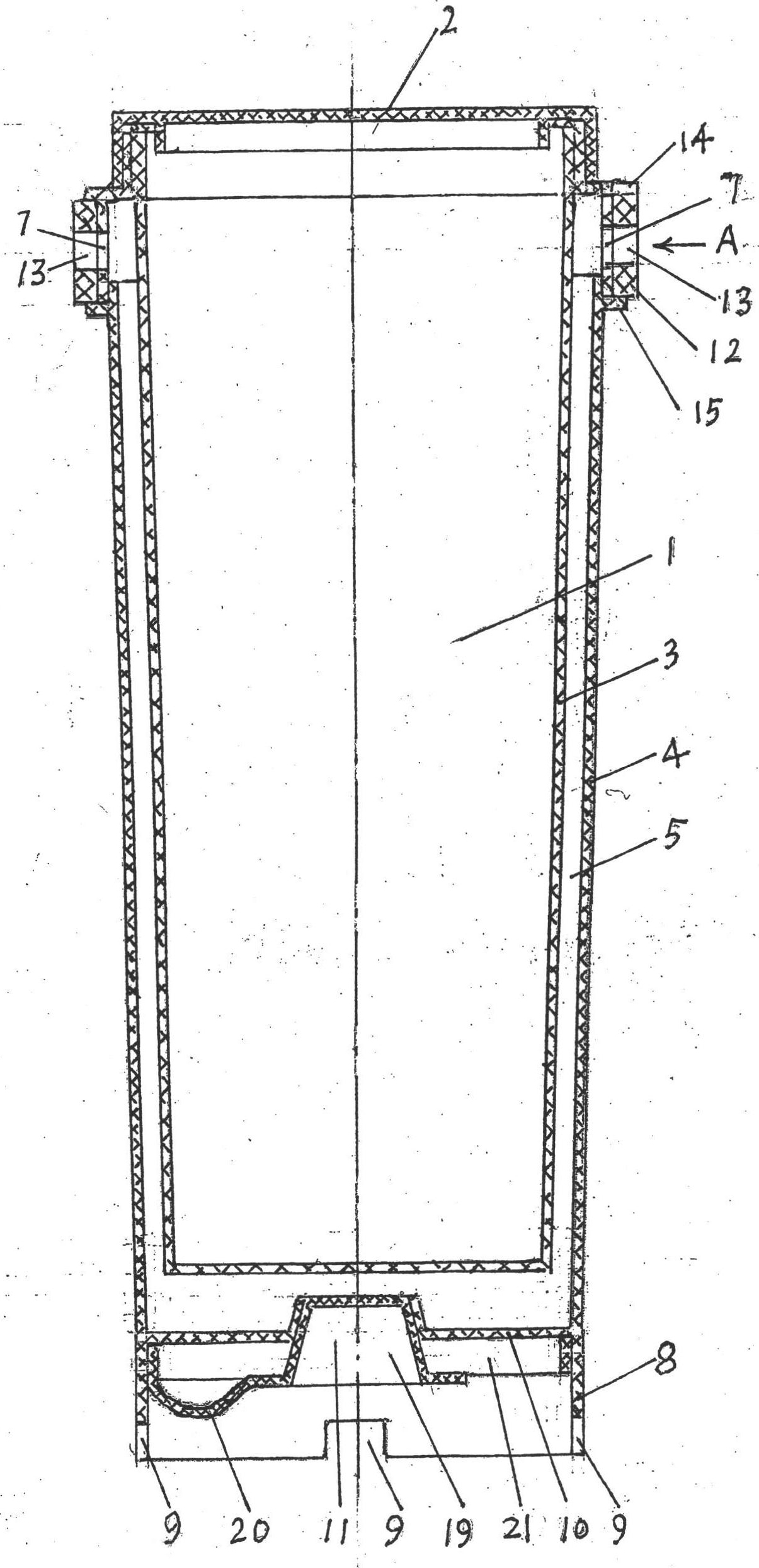
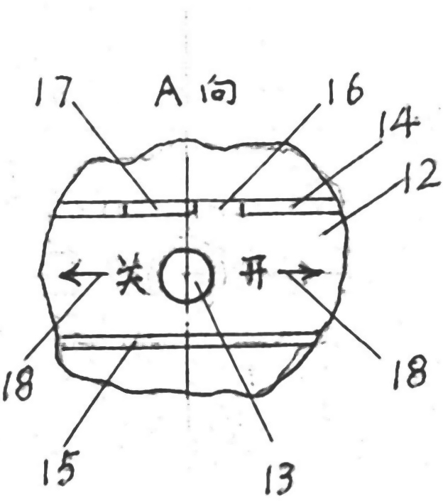
[0027] Embodiment 1 The thermal insulation cup capable of rapid cooling and rapid heating is as figure 1 , figure 2 shown. In this case, the thermos cup capable of quick cooling and quick heating includes a cup body 1 and a cup cover 2. The cup body 1 includes an inner layer 3, an outer shell 4, and a gap layer 5 inside the outer shell 4 outside the inner layer 3. The bottom of the cup body 1 is set There is a bottom hole, the bottom hole is connected with the bottom of the gap layer 5, the upper hole 7 is arranged at the higher part of the shell 4, and the upper hole 7 is connected with the higher part of the gap layer 5, and the skirt 8 of the shell 4 is lower than the bottom hole. Ventilation gap 9 is provided, shell 4 has concave bottom surface 10, bottom hole is set on the concave bottom surface 10 of shell 4, bottom hole is provided with bottom hole cover 11, upper hole 7 is provided with upper hole switch 12.
[0028] This example thermos cup is made of plastic. Mos...
Embodiment 2
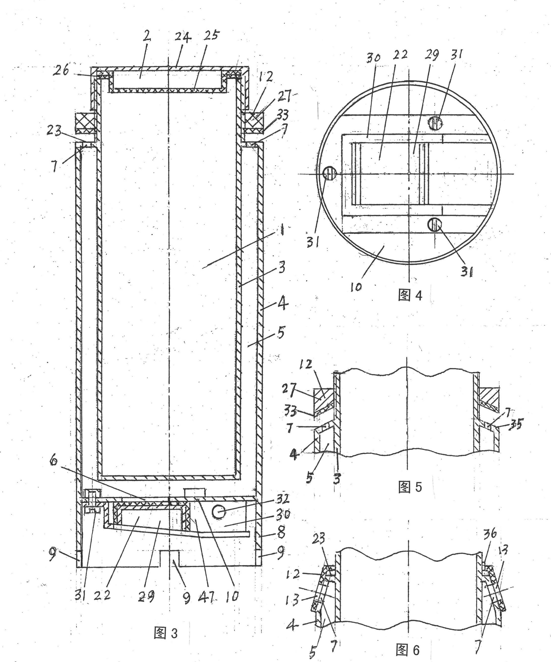
[0033] Embodiment 2 The thermal insulation cup capable of rapid cooling and rapid heating is as image 3 , Figure 4 shown. In this case, the thermos cup capable of quick cooling and quick heating includes a cup body 1 and a cup cover 2. The cup body 1 includes an inner layer 3, an outer shell 4, and a gap layer 5 inside the outer shell 4 outside the inner layer 3. The bottom of the cup body 1 is set There is a bottom hole 6, which communicates with the bottom of the gap layer 5, an upper hole 7 is arranged at a higher part of the shell 4, and the upper hole 7 communicates with a higher part of the gap layer 5, and the skirt of the shell 4 is lower than the bottom hole 6 The part 8 is provided with a ventilation gap 9, the shell 4 has a concave bottom surface 10, the bottom hole 6 is arranged on the concave bottom surface 10 of the shell 4, the bottom hole 6 is provided with a bottom hole switch 22, and the upper hole 7 is provided with an upper hole switch 12 .
[0034] Cu...
Embodiment 3
[0038] The thermos cup of embodiment 3 is a variant of the thermos cup of embodiment 2. see image 3 , Figure 5 , the difference between embodiment 3 and embodiment 2 is as Figure 5 shown. The difference between the thermos cup of this example and the thermos cup of Embodiment 2 is that: the horizontal annular band 23 of the shell 4 in Embodiment 2 has become the conical surface segment 35 in Embodiment 3. The flat screw compression upper hole switch 12 in embodiment 2 has become the cone screw compression upper hole switch 12 of embodiment 3.
[0039] Eight circular holes evenly distributed are made on the shell 4 conical surface section 35, and they are exactly the upper hole 7 that shell 4 is provided with higher. This upper hole 7 communicates with the upper end of the gap layer 5 , that is, communicates with the higher part of the gap layer 5 . The part of the outer shell 4 on the conical surface section 35 is also the exposed part of the inner layer 3 . The shell...
PUM
 Abstract
Description
Claims
Application Information
 - R&D
- Intellectual Property
- Life Sciences
- Materials
- Tech Scout
- Unparalleled Data Quality
- Higher Quality Content
- 60% Fewer Hallucinations
Browse by: Latest US Patents, China's latest patents, Technical Efficacy Thesaurus, Application Domain, Technology Topic, Popular Technical Reports.
© 2025 PatSnap. All rights reserved.Legal|Privacy policy|Modern Slavery Act Transparency Statement|Sitemap|About US| Contact US: help@patsnap.com


