Multi-cylinder synchronous structure of hydraulic system

A technology of hydraulic system and hydraulic cylinder, applied in the field of multi-cylinder synchronous structure of hydraulic system, can solve the problems of inconsistent friction gap, error of cylinder machining accuracy, and difficulty in controlling the parallelism of sliders.

Inactive Publication Date: 2012-07-25
NANTONG FORGING EQUIP
0 Cites 0 Cited by

AI-Extracted Technical Summary

Problems solved by technology

Due to the certain error in the machining accuracy of each oil cylinder, the friction gaps in various places are inconsist...

Abstract

The invention relates to a multi-cylinder synchronous structure of a hydraulic system, which comprises a hydraulic cylinder group I and a hydraulic cylinder group II. A system I and a system II supply liquid to the hydraulic cylinder group I and the hydraulic cylinder group II respectively. The multi-cylinder synchronous structure is characterized in that a device for controlling the oil drainage quantity of a return cavity of the hydraulic cylinder group II based on the pressure of a return cavity of the hydraulic cylinder group I is arranged on the return cavity of the hydraulic cylinder group II. The system I and the system II correspondingly supply oil in the same quantity to upper cavities of hydraulic cylinders involved in pressing, the device for controlling the oil drainage quantity of the return cavity of the hydraulic cylinder group II controls the oil drainage quantity by means of comparing the pressure of the return cavity of the hydraulic cylinder group I with the pressure of the return cavity of the hydraulic cylinder group II, and uniform movement of the hydraulic cylinders in the hydraulic cylinder group I and the hydraulic cylinder group II is ensured, so that the balance level of a whole movable beam is controlled.

Application Domain

Servomotors

Technology Topic

Control engineeringHydraulic cylinder

Image

  • Multi-cylinder synchronous structure of hydraulic system
  • Multi-cylinder synchronous structure of hydraulic system
  • Multi-cylinder synchronous structure of hydraulic system

Examples

  • Experimental program(1)

Example Embodiment

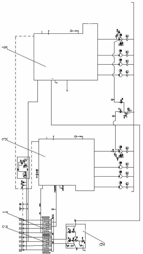
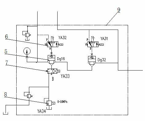
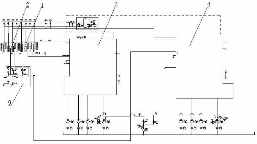
[0009] Such as figure 1 , 2 As shown, hydraulic cylinder group I1, hydraulic cylinder group II2, system I3, system II4, plug-in 5, solenoid ball valve A6, two-position four-way solenoid valve B7, and proportional pressure regulating valve 8.
[0010] The above-mentioned hydraulic cylinder group I1 and hydraulic cylinder group II2 are supplied by system I3 and system II4 respectively.
[0011] The hydraulic cylinder group II2 return cavity is provided with a device for controlling the oil discharge volume of the hydraulic cylinder group II2 return cavity based on the pressure of the hydraulic cylinder group I1 return cavity.
[0012] The return cavity oil discharge control device 9 includes a plug-in 5, a solenoid ball valve A6, a two-position four-way solenoid valve B7, and a proportional pressure regulating valve 8. The plug-in 5 has three oil ports a, b, and c. When there is pressure, the a port and the b port are disconnected, and when the c port has no pressure, the a port and the b port are connected. The a port of plug-in 5 is directly connected with the hydraulic cylinder return cavity of the hydraulic cylinder group II2, the b port is connected to the oil inlet of the two-position four-way solenoid valve B7, and the c port is between the hydraulic cylinder return cavity of the hydraulic cylinder group II2 A solenoid ball valve A6 is set, and the solenoid ball valve A6 is used to open and close the c port of the plug-in 5 to fill or drain oil according to the programmable controller signal.
[0013] The oil outlet of the two-position four-way solenoid valve B7 is connected to the proportional pressure regulating valve 8. The proportional pressure regulating valve 8 can adjust the oil discharge opening according to the current signal of the programmable controller.
[0014] Working principle: During compression, the upper chambers of the hydraulic cylinders participating in the compression in the hydraulic cylinder group I1 and the hydraulic cylinder group II2 are provided with the same amount of oil correspondingly by the system I3 and the system II4, and at the same time, the return cavity of the hydraulic cylinder discharges oil.
[0015] In the process of draining oil, the hydraulic cylinder group II 2 is drained by the return cavity drain volume control device. Specifically: solenoid ball valve A6, two-position four-way solenoid valve B7 and proportional pressure regulating valve 8 are all energized, plug-in 5 c The pressure of the oil ports is relieved, so that the ports a and b are connected. The hydraulic oil in the return chamber of the hydraulic cylinder group II 2 passes through the two-position four-way solenoid valve B7 and is discharged by the proportional pressure regulating valve 8.
[0016] The oil volume of the return cavity of the hydraulic cylinder group II 2 is determined by the opening of the proportional pressure regulating valve 8. Specifically: the measured hydraulic cylinder group II 2 return cavity pressure signal is output to the programmable controller, and the programmable controller uses the hydraulic cylinder group Ⅰ1 The pressure in the return chamber is compared as the benchmark, and the proportional pressure regulating valve 8 is given different current control signals according to the program setting plan, so as to control the opening of the proportional pressure regulating valve 8, so that the hydraulic cylinder group I and the hydraulic cylinder group II All hydraulic cylinders move in unison, thus controlling the balance of the entire moving beam.

PUM

no PUM

Description & Claims & Application Information

We can also present the details of the Description, Claims and Application information to help users get a comprehensive understanding of the technical details of the patent, such as background art, summary of invention, brief description of drawings, description of embodiments, and other original content. On the other hand, users can also determine the specific scope of protection of the technology through the list of claims; as well as understand the changes in the life cycle of the technology with the presentation of the patent timeline. Login to view more.
Why Eureka
Try Eureka