Supercharge Your Innovation With Domain-Expert AI Agents!

Floor cleaning heads for surface cleaning equipment

A floor cleaning and surface cleaning technology, applied in the direction of machine parts, suction nozzles, etc., can solve the problem of not improving the suction efficiency, water and detergent consumption, being opened or both are closed, and the two scrapers rotate inconsistently before and after, etc. problems, to achieve the effect of reducing the frequency of cleaning or replacing cleaning tools

Active Publication Date: 2017-08-25
SUZHOU DELAI ELECTRICAL APPLIANCE
View PDF3 Cites 0 Cited by
  • Summary
  • Abstract
  • Description
  • Claims
  • Application Information

AI Technical Summary

Problems solved by technology

In this solution, since the scrapers act independently, it is easy to cause the two scrapers to rotate inconsistently back and forth, so that the two suction ports are both opened or closed, so that the improvement of suction efficiency and the reduction of water and water cannot be achieved. The purpose of detergent consumption

Method used


Image

  • Floor cleaning heads for surface cleaning equipment
  • Floor cleaning heads for surface cleaning equipment
  • Floor cleaning heads for surface cleaning equipment

Examples


Embodiment Construction

[0041] In order to describe the technical content, structural features, achieved goals and effects of the invention in detail, the following will be described in detail in conjunction with the embodiments and accompanying drawings.

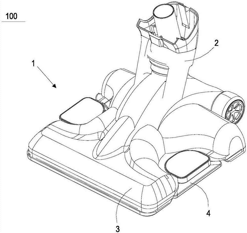
[0042] like figure 1 Shown is a floor cleaning head 100 for a steam mop, the floor cleaning head 100 is adapted to move back and forth over the floor to be cleaned. The floor cleaning head 100 has a cleaning head body 1, and the rear portion of the cleaning head body 1 is provided with a rotating joint 2, which is used to be connected with an upright handle assembly (not shown in the figure) of a steam mop, standing upright The handle assembly is configured to push the cleaning head body 1 forward and backward. The cleaning head body 1 has a first casing 3 and a second casing 4 arranged up and down, and the first casing 3 and the second casing 4 are fixed by mechanical fasteners or fastened. In this example, the rotary joint 2 is installed at th...


PUM


Abstract

The invention relates to a floor cleaning head of surface cleaning equipment, comprising a cleaning head body, a cleaning tool located at the bottom of the cleaning head body, a pair of suction ports and a connecting rod, the pair of suction ports are respectively distributed on the front and rear sides of the cleaning tool, and a pair of A damper for opening and closing the suction port is provided at the suction port, and the upper part of a pair of dampers is provided with a rotating installation part suitable for rotating back and forth with the cleaning head body, and at least one of the pair of dampers is provided with a lower part suitable for The friction part that is in contact with the ground to be cleaned and can be applied by the ground to be cleaned; the front and rear ends of the connecting rod are respectively fixed to the upper parts of a pair of dampers. When one of the pair of dampers rotates, the connecting rod Pushing the other damper also turns in the same direction. By connecting the two dampers together by means of the connecting rod, the rotation of the two dampers can be kept consistent when the cleaning head is moved forward or pulled backward.

Description

technical field [0001] The invention relates to a floor cleaning head of a surface cleaning device. Background technique [0002] A steam mop is a common device used to clean hard surfaces (such as tiles, floors, etc.). A common steam mop has a base and a vertical handle, and a steam spray hole and a dirt suction port are arranged at the bottom of the base, a cleaning cloth is installed on the bottom of the steam spray hole, and a cleaning cloth is also arranged on the base and the vertical handle. The steam supply system consists of a water tank, a steam generator, a pump or valve connecting the water tank and the steam generator, and a steam output channel connecting the steam generator and the steam injection hole, and a vacuum motor, a dirt tank, and a dirt tank connected to the dirt tank. The dirt suction system formed by the dirt suction channel of the dirt suction port. When a steam mop is in operation, steam is ultimately applied to the cleaning cloth, which is wip...

Claims


Application Information

Patent Timeline
Patent Type & Authority Patents(China)
IPC IPC(8): A47L9/02A47L11/40
Inventor 卞庄
Owner SUZHOU DELAI ELECTRICAL APPLIANCE
Features
  • R&D
  • Intellectual Property
  • Life Sciences
  • Materials
  • Tech Scout
  • Unparalleled Data Quality
  • Higher Quality Content
  • 60% Fewer Hallucinations
Learn More