Mounting structure of electric energy meter

A technology for the installation and installation structure of electric energy meters, which is applied in the direction of measuring devices, measuring electrical variables, instruments, etc., can solve the problems of wiring safety impact, reducing space utilization, increasing workload, etc., and achieves convenience, visibility and reliability. Operability, improvement of space utilization, and effect of reducing installation space

Inactive Publication Date: 2012-07-25
无锡双欢电气有限公司
View PDF7 Cites 0 Cited by
  • Summary
  • Abstract
  • Description
  • Claims
  • Application Information

AI Technical Summary

Problems solved by technology

[0002] At present, the hanging-mounted electric energy meters (such as electronic three-phase multi-rate electric energy meters) are all hung on the mesh panel in the instrument room, which is large in size and takes up a lot of space, which reduces the space utilization rate; The meter must be viewed through the observation window. The interior of the instrument room is relatively dark, and the readings of the meter must be seen with the help of peripheral light, which is not very visible. In addition, there are operation buttons on the electric energy meter, which need to be opened by opening the door panel of the instrument room. It is very troublesome to operate, the workload increases, and the operability is greatly reduced
If the energy meter is hung on the door panel of the instrument room, the aesthetics will be reduced due to the thickness of this type of energy meter, and the overall exposure of the energy meter will affect the wiring and safety.

Method used


Image

  • Mounting structure of electric energy meter
  • Mounting structure of electric energy meter
  • Mounting structure of electric energy meter

Examples


Embodiment Construction

[0012] The specific embodiments of the present invention will be further described below in conjunction with the accompanying drawings.

[0013] The following embodiments illustrate the installation of an electronic three-phase multi-rate electric energy meter.

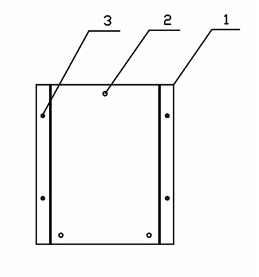
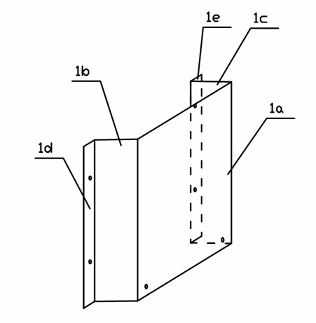
[0014] Such as figure 1 , figure 2 As shown, a piece of aluminum-zinc coated steel plate with a length and width of 234*270mm (this size depends on the external dimensions of the electronic three-phase multi-rate electric energy meter) is selected, and the whole plate is made into a bridge-like bridge shape by folding both sides. Mounting plate 1, the bridge type mounting plate 1 has a first plane 1a, the two sides of the first plane 1a are vertically bent to form a first vertical plane 1b and a second vertical plane 1c, the two sides of the first vertical plane 1b and the second vertical plane 1c The second plane 1d and the third plane 1e are formed by vertical bending respectively.

[0015] The first plane 1a is...


PUM


Abstract

The invention discloses a mounting structure of an electric energy meter, comprising a bridge type mounting plate and a door sheet, wherein the bridge type mounting plate is provided with a first plane; the two sides of the first plane are vertically bent to form a first vertical plane and a second vertical plane; the two sides of each of the first vertical plane and the second vertical plane are vertically bent to form a second plane and a third plane respectively; an electric energy meter mounting hole is formed on the first plane and the electric energy meter is fixed to the bridge type mounting plate via the electric energy meter mounting hole; door sheet mounting holes are formed on the second plane and the third plane and the bridge type mounting plate is fixed to the rear surface of the door sheet via the door sheet mounting holes; electric energy meter panel holes are formed on the door sheet and the bridge type mounting plate in corresponding positions; and the panel of the electric energy meter is embedded in the electric energy meter panel hole. The mounting structure of the electric energy meter provided by the invention reduces the mounting space of elements in a cabinet and improves the space utilization ratio on the basis of ensuring a gap and a safety distance; and enough overhaul space is remained, which is convenient for users to observe and operate the electric energy meter.

Description

technical field [0001] The invention relates to an installation structure of an electric energy meter in a meter room. Background technique [0002] At present, the hanging-mounted electric energy meters (such as electronic three-phase multi-rate electric energy meters) are all hung on the mesh panel in the instrument room, which is large in size and takes up a lot of space, which reduces the space utilization rate; The meter must be viewed through the observation window. The interior of the instrument room is relatively dark, and the readings of the meter must be seen with the help of peripheral light, which is not very visible. In addition, there are operation buttons on the electric energy meter, which need to be opened by opening the door panel of the instrument room. Its operation is very troublesome, the workload increases, and the operability is greatly reduced. If the energy meter is hung on the door panel of the instrument room, the aesthetics will be reduced due t...

Claims


Application Information

Patent Timeline
Patent Type & Authority Applications(China)
IPC IPC(8): G01R11/00G01R11/04
Inventor 钱莹黄银霞刘华徐志琴庄群养王彦珠张晓英魏征
Owner 无锡双欢电气有限公司
Why Eureka
Try Eureka