Descender

A technology for outer sleeves and mandrels, which is applied to machine parts, life-saving equipment, and carpet cleaning, etc. It can solve the problems of reduced friction force around ropes, increased friction force around ropes, and inconvenient use of rod-type descenders, etc., and achieves Simple operation effect

Inactive Publication Date: 2012-08-01
何少敦
View PDF6 Cites 3 Cited by
  • Summary
  • Abstract
  • Description
  • Claims
  • Application Information

AI Technical Summary

Benefits of technology

This technology allows users to control their movement by hand without having them have physical contact with it while still being able to make sure they are safely falling off from high places like floors when needed for maintenance purposes.

Problems solved by technology

The technical issue addressed in this patented text relates to improving safer construction methods while maintaining ease with regards to ascenders during cleanup operations on building exteriors.

Method used


Image

  • Descender
  • Descender
  • Descender

Examples


Embodiment Construction

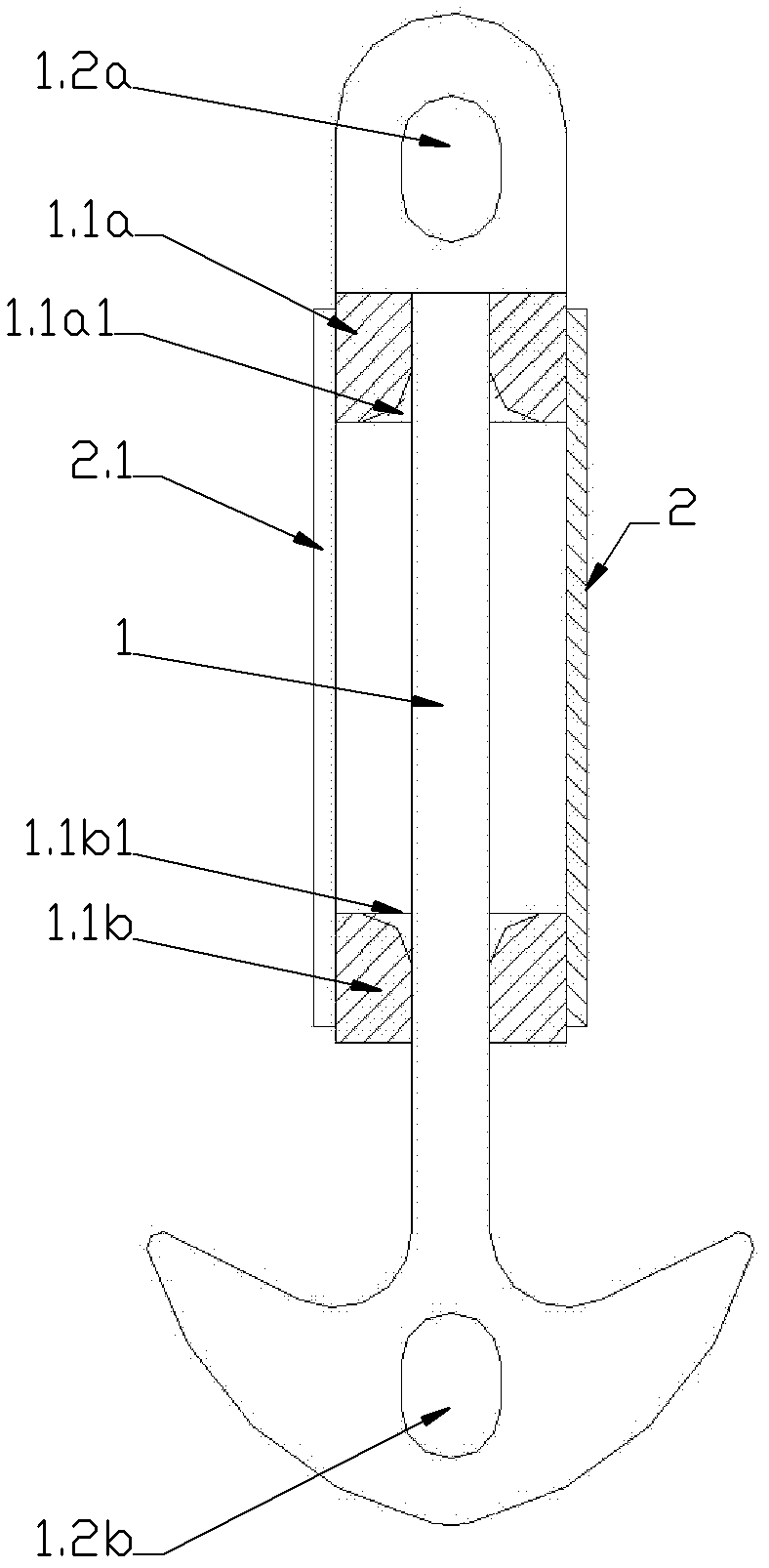
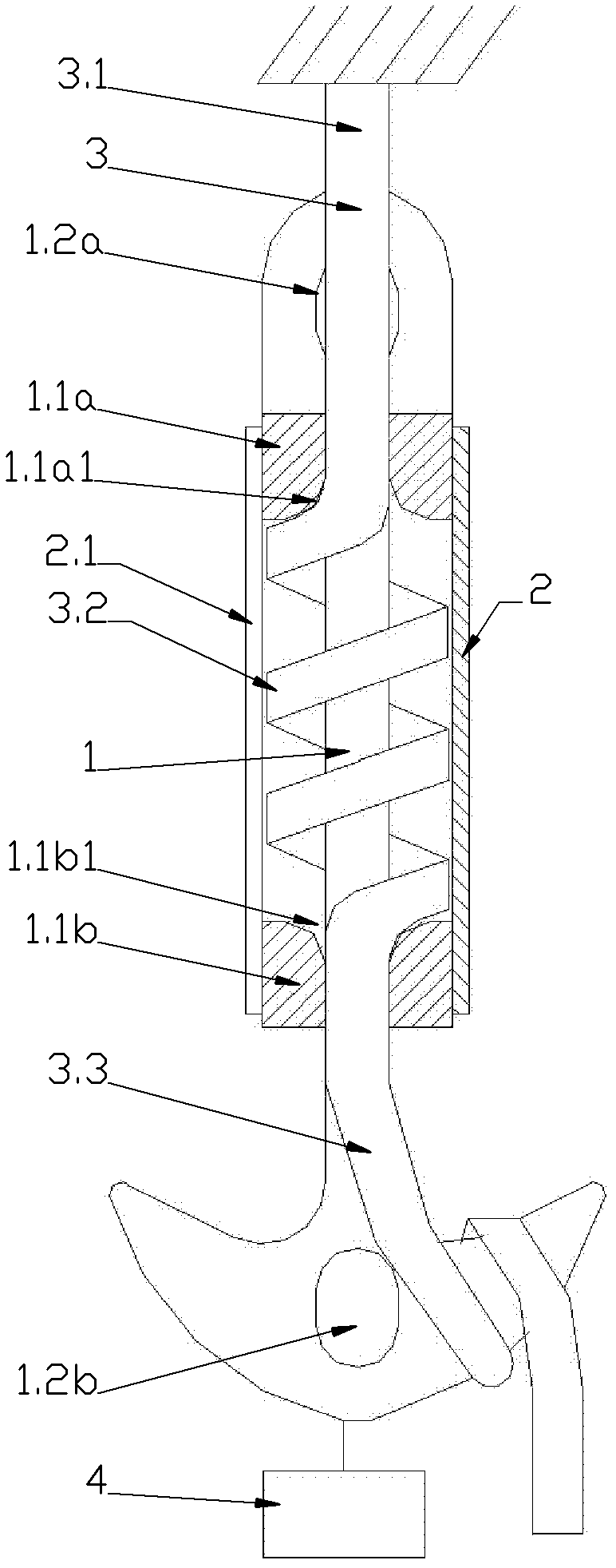
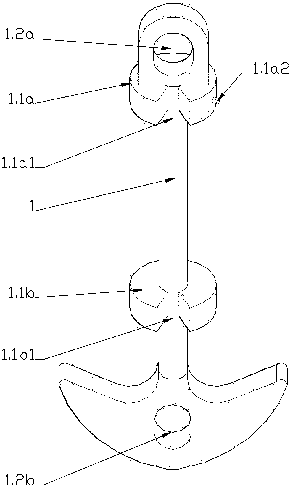
[0030] figure 1 , figure 2 , image 3 , Figure 4 , Figure 5 , Image 6 , Figure 7 It is a structural schematic diagram of an existing rod-type descender; where figure 1 , figure 2 , Figure 7 is a schematic plan view of the structure, image 3 , Figure 4 , Figure 5 is a schematic diagram of the local structure, Image 6 is the external stereogram, figure 2 , Figure 7 It is the roping diagram of the working rope when in use. As shown in the figure, the existing rod-type descender is composed of a mandrel 1 and an outer sleeve 2. The mandrel 1 is provided with an upper end 1.1a and a lower end 1.1b, and the two ends of the mandrel 1 are provided with hanging The hook mouth 1.2a, the lower hook mouth 1.2b, the upper end 1.1a and the lower end 1.1b are respectively provided with an upper sliding rope opening 1.1a1 and a lower sliding rope opening 1.1b1, and an outer sleeve is also arranged on the upper end 1.1a The first positioning part 1.1a2 of 2, the outer...


PUM


Abstract

The invention relates to a descender. The invention provides a bar descender so as to solve the problem that the conventional bar descender is inconvenient to use. The descender is formed by combining a core shaft and an outer sleeve, wherein an outer sleeve rope-sliding port is formed on the outer sleeve; a rope-pressing ring is arranged on the outer sleeve; the rope-pressing ring can slide up and down under the control of hands; when the rope-pressing ring is positioned at the rope-sliding port, the winding rope on the core shaft is extruded, the friction force of the winding rope is increased and a human body stops descending; and when the rope-pressing ring moves upwards and departs from the rope-sliding port, the winding rope is not pressed, the friction force of the winding rope is reduced and the human body descends. The descender can serve as a hanging tool applied to construction, such as cleaning, decorating and the like of building outer walls, can serve as a hanging tool applied to building fire-fighting life saving, rescue or aloft life saving and work, and can also serve as special equipment applied to airborne landing of staff.

Description


Claims


Application Information

Patent Timeline
Owner 何少敦
Why Eureka
Try Eureka