Hydrodynamic tooth washing apparatus
A dental irrigator and hydrodynamic technology, which is applied in the direction of devices such as cleaning dental cavities, can solve the problems of difficult home use and high cost, and achieve the effects of cost saving, increased strength, and favorable promotion.
- Summary
- Abstract
- Description
- Claims
- Application Information
AI Technical Summary
Problems solved by technology
Method used
Image

Examples
Embodiment Construction
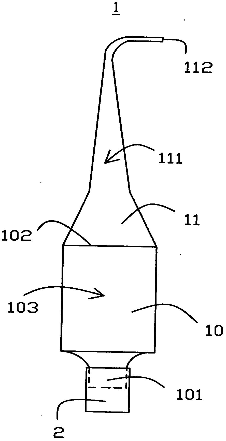
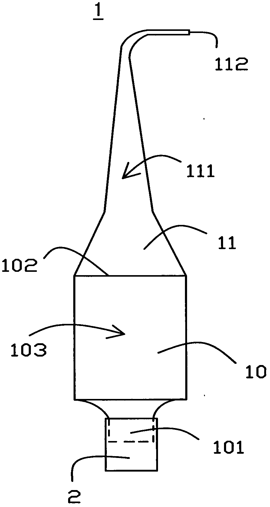
[0020] The specific implementation manners of the present invention will be described in further detail below with reference to the accompanying drawings.
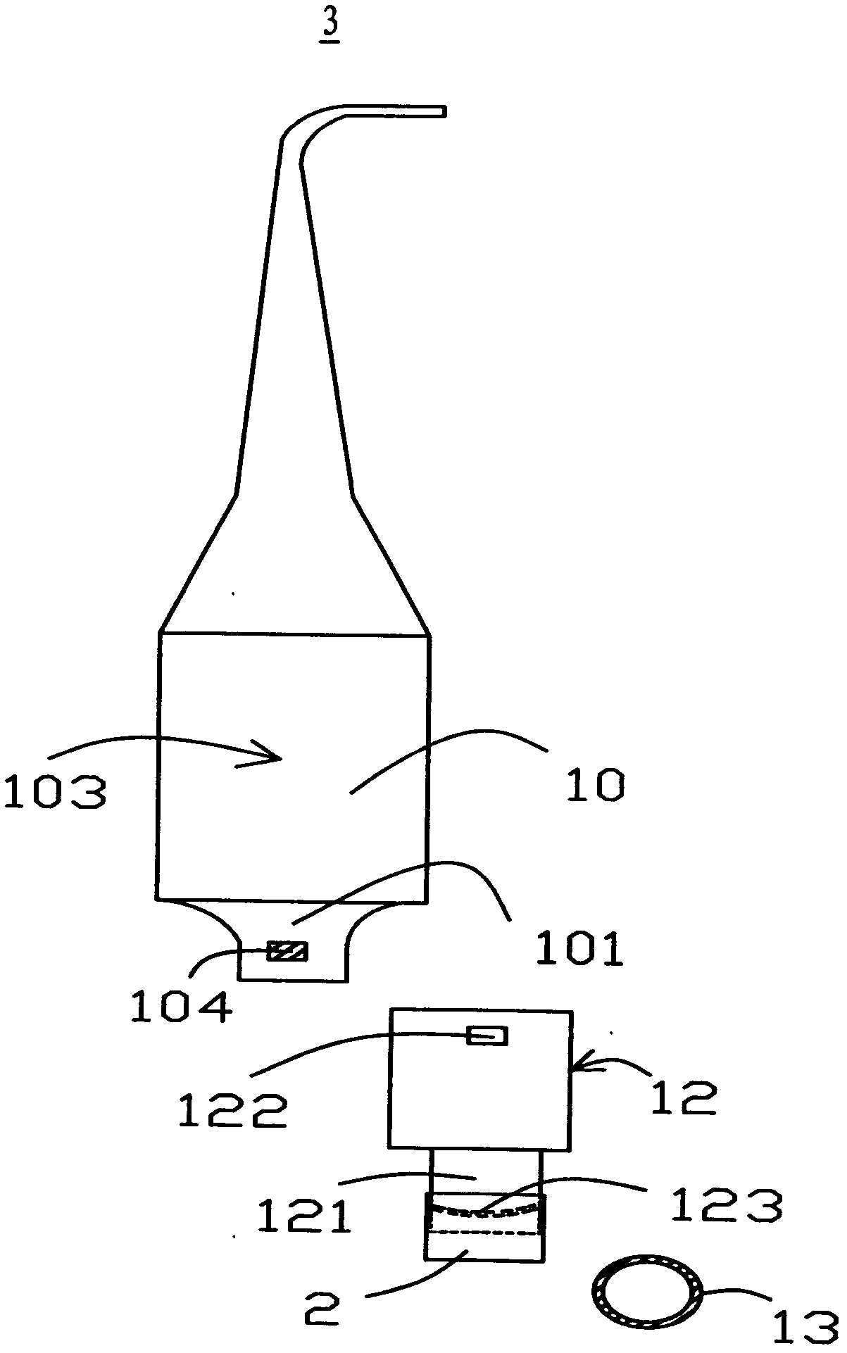
[0021] figure 1 A schematic structural view of a water-driven dental flosser according to an embodiment of the present invention is shown. refer to figure 1 , The hydraulic flosser 1 includes: a handle 10 and a nozzle 11 . Wherein, the handle 10 has a water inlet 101 , a water outlet 102 and a pressurized chamber 103 , and the water inlet 101 can be connected with a hose 2 to connect to a water source. It should be particularly noted here that the water source can be a domestic tap water source, and it must be ensured that the position of the water source is higher than the position of the handle 10 . In order to facilitate the connection of the hose 2 to the handle 10 , threads can be provided on the outer surface of the handle 10 . The pressurized chamber 103 communicates with the water inlet 101 and the water outlet...
PUM
| Property | Measurement | Unit |
|---|---|---|
| Diameter | aaaaa | aaaaa |
| Diameter | aaaaa | aaaaa |
Abstract
Description
Claims
Application Information
PatSnap Eureka turns technology decisions into work you can execute. Powered by our Innovation Knowledge Graph, it runs expert workflows across engineering, life sciences, materials and intellectual property. Get your review-ready output in minutes.


