Multi-field-coupled coal mine dynamic disaster large-scale simulation testing method

A dynamic disaster and simulation test technology, which is applied in the direction of material analysis using acoustic wave emission technology, can solve the problems of small model size, low degree of automation, and low sealing of devices

Active Publication Date: 2012-08-01
CHONGQING UNIV
View PDF2 Cites 24 Cited by
  • Summary
  • Abstract
  • Description
  • Claims
  • Application Information

AI Technical Summary

Problems solved by technology

[0003] In the prior art, the test devices for simulating coal mine dynamic disasters mainly have the following problems: (1) The size of the model used is small, and the development process of simulating dynamic disasters has a certain space limitation; (2) The degree of automation of device installation is low ; (3) The sealing of the device is not high, the simulated gas pressure is not high, and the pressure of the simulated gas in the test cannot be close to the situation on site; (4) The opening speed of the protrusion baffle is slow or there is a certain delay, which affects to a certain extent The time and intensity of coal and gas outburst are not known, so there are still differences between the actual simulation situation and the real underground coal and gas outburst; (5) The simulated in-situ stress cannot fully simulate the local stress concentration of the mining face caused by mining activities; (6) The coal and rock mass parameters inside the outburst mold are not collected enough. In most cases, only the temperature and gas pressure are collected, and the collection point is relatively single. It is impossible to analyze and study the stress and temperature development laws inside the coal and rock mass before and after the coal mine dynamic disaster.

Method used


Image

  • Multi-field-coupled coal mine dynamic disaster large-scale simulation testing method
  • Multi-field-coupled coal mine dynamic disaster large-scale simulation testing method
  • Multi-field-coupled coal mine dynamic disaster large-scale simulation testing method

Examples


Embodiment Construction

[0045] Below in conjunction with accompanying drawing and embodiment the present invention will be further described:

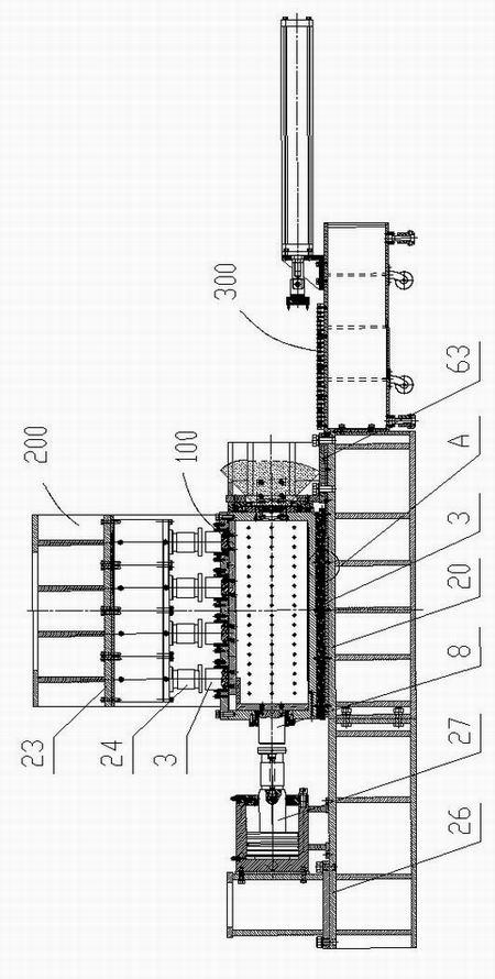
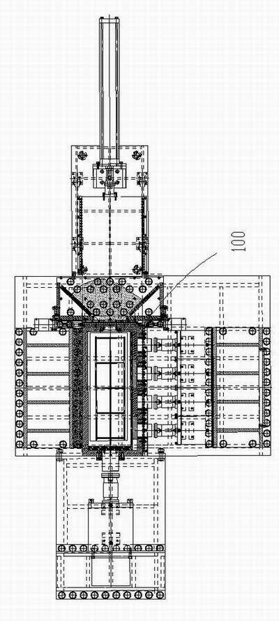
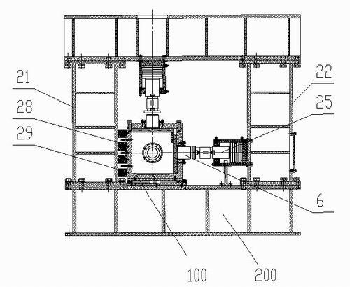
[0046] like Figure 1 to Figure 4 As shown, a large-scale multi-field coupling coal mine dynamic disaster simulation test system includes a frame 200 and a test piece box 100 placed on the frame 200 .

[0047] The test piece box 100 includes a box body 1, the top of the left box panel, right box panel, front box panel and rear box panel of the box body 1 is a ladder structure, and the height of the ladder structure near the inner cavity of the box body 1 is greater than that far away from the box body 1. The height of the cavity, so that the top of the casing 1 forms a boss 48.

[0048] like Figure 5 to Figure 11 As shown, the cover plate 4 is fastened with the box body 1 . At the boss 48 , a gasket 49 is provided between the cover plate 4 and the box body 1 , and the cover plate 4 and the box body 1 are fixedly connected at the boss 48 by bolts.

[0049...


PUM


Abstract

The invention discloses a multi-field-coupled coal mine dynamic disaster large-scale simulation testing method, which includes the following steps: (1) completing formation and assembly of coal and rock inside a test piece box, connection of sensors and circuits and connection of a gas circuit; (2) placing the test piece box in a pressurizing system at a preset position, pressurizing the test piece box in the X-axis, the Y-axis and the Z-axis; (3) starting a data acquisition system; (4) degassing; (5) charging gas; and (6) outbursting. The method disclosed by the invention can monitor coal and rock gas pressure, ground stress, temperature variation of a coal and rock body as well as space-time evolution law of an acoustic emission signal of the coal and rock body before and after the occurrence of a coal mine dynamic disaster, and achieves the purposes of studying internal relations among a stress field, a seepage field, a temperature field and a fracture field as well as studying mutually coupled action mechanism thereof during the coal mine dynamic disaster, thereby revealing the occurrence mechanism of the coal mine dynamic disaster and providing theoretic base for prevention and control of the coal mine dynamic disaster.

Description

technical field [0001] The invention relates to a test method for simulating the coal mine dynamic disaster process under the multi-field coupling mechanism. Background technique [0002] Coal mine dynamic disasters are coal and rock masses with a large amount of elastic energy accumulated in a high-stress state in the process of coal mine mining. Under certain conditions, the coal and rock mass suddenly breaks, falls or is thrown, causing the energy to be released suddenly, presenting sound, vibration and gas. Extremely complex dynamic phenomena with obvious dynamic effects such as waves, which mainly have three main forms: coal rock and gas outburst, rock burst and large-scale roof fall, which seriously threaten the safe production of coal mines and the safety of miners' lives. The occurrence of dynamic disasters is difficult to predict and grasp, and its internal pathways and mechanisms have not been fully understood by human beings. Moreover, with the increasing depth of...

Claims


Application Information

Patent Timeline
Patent Type & Authority Applications(China)
IPC IPC(8): G01N29/14
Inventor 许江尹光志黄滚王维忠彭守建蒋长宝张东明刘东李波波叶桂兵
Owner CHONGQING UNIV
Why Eureka
Try Eureka