Real-time camera tracking using depth maps

A technology of depth camera and depth map, applied in the field of image technology, can solve problems such as accuracy, robustness and speed limit

Active Publication Date: 2012-08-01
MICROSOFT TECH LICENSING LLC
View PDF2 Cites 31 Cited by
  • Summary
  • Abstract
  • Description
  • Claims
  • Application Information

AI Technical Summary

Problems solved by technology

Existing solutions are limited in accuracy, robustness and speed

Method used


Image

  • Real-time camera tracking using depth maps
  • Real-time camera tracking using depth maps
  • Real-time camera tracking using depth maps

Examples


Embodiment Construction

[0019] The detailed description provided below in connection with the accompanying drawings is intended as a description of examples of the invention and is not intended to represent the only forms in which examples of the invention may be constructed or used. This description sets forth the functionality of an example of the invention, and a sequence of steps for building and operating the example of the invention. However, the same or equivalent functions and sequences can be implemented by different examples.

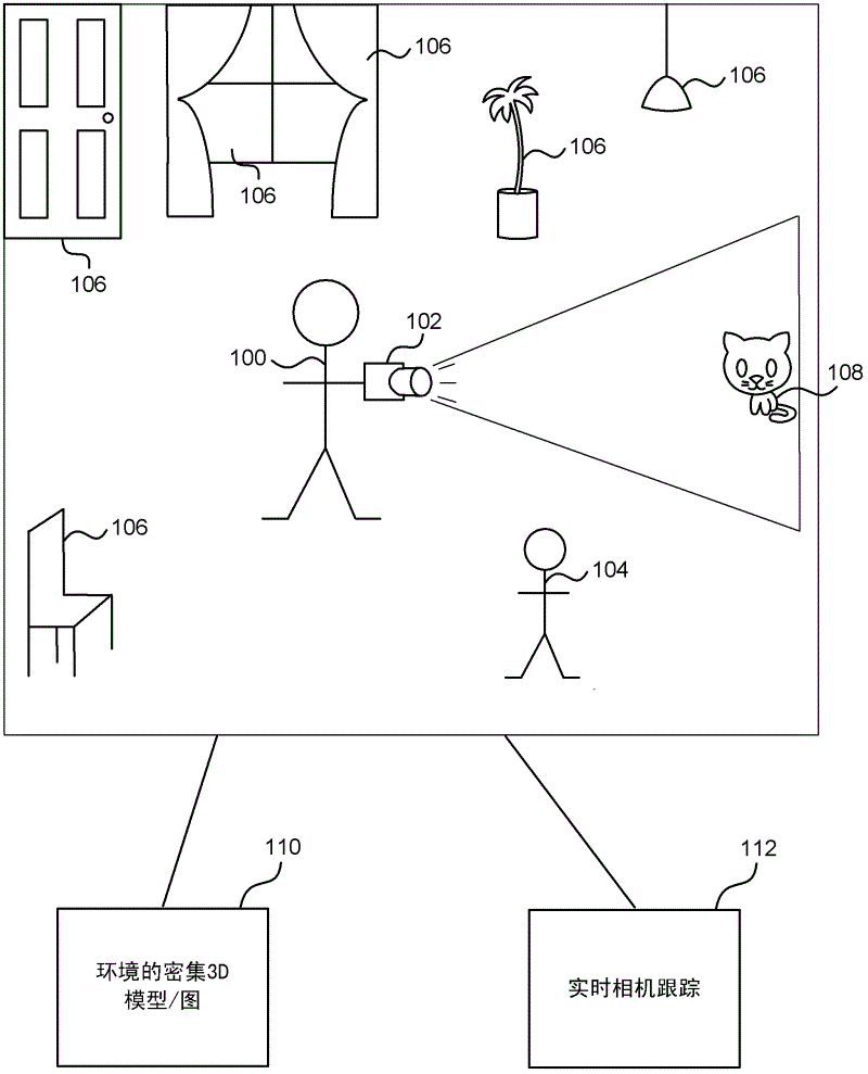
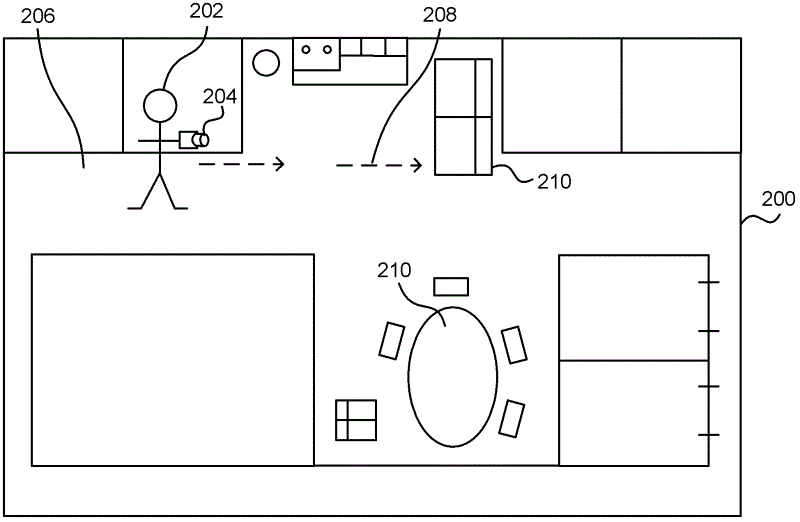
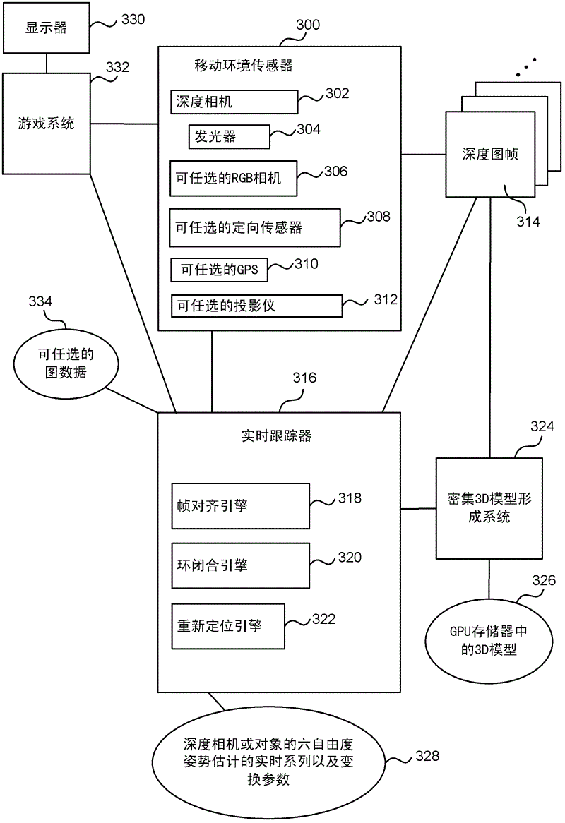
[0020] Although examples of the invention are described herein and shown implemented in a real-time camera tracking system using depth images obtained from mobile depth cameras that emit and capture infrared light, the systems described are by way of example and not limitation to provide. Those skilled in the art will understand that examples of the present invention are suitable for application in various types of real-time camera tracking systems, including but no...


PUM


Abstract

Real-time camera tracking using depth maps is described. In an embodiment depth map frames are captured by a mobile depth camera at over 20 frames per second and used to dynamically update in real-time a set of registration parameters which specify how the mobile depth camera has moved. In examples the real-time camera tracking output is used for computer game applications and robotics. In an example, an iterative closest point process is used with projective data association and a point-to-plane error metric in order to compute the updated registration parameters. In an example, a graphics processing unit (GPU) implementation is used to optimize the error metric in real-time. In some embodiments, a dense 3D model of the mobile camera environment is used.

Description

technical field [0001] The present invention relates to image technology, in particular to camera tracking technology. Background technique [0002] For many applications, it is valuable to be able to track the orientation and position of a camera as it moves through the environment. For example, in robotics, vehicle navigation, computer game applications, medical applications, and other problem domains. Previous approaches have involved using color images captured by a moving camera, identifying features such as lines and edges in those images, and capturing this information in a sequence of color images captured by the camera to try and evaluate relative camera positions. Existing schemes are limited in accuracy, robustness, and speed. However, for many applications, accurate camera tracking is required in real time, for example so that a robot can successfully move around its environment. [0003] The embodiments described below are not limited to implementations that ...

Claims


Application Information

Patent Timeline
Patent Type & Authority Applications(China)
IPC IPC(8): G06T7/20G06T7/00
CPCG06T7/2046G06T7/20A63F13/00G06K9/00A63F2300/1087G06T2207/30244A63F2300/69G06T2207/10028A63F13/06G06T2207/10048G06T7/0024G06T7/00G06T7/30G06T7/251A63F13/42A63F13/213A63F13/65G06V20/10G06F18/00
Inventor R·纽科姆S·伊扎迪D·莫利尼奥克斯O·希利格斯D·金J·D·J·肖顿P·科利A·费茨吉本S·E·豪杰斯D·A·巴特勒
Owner MICROSOFT TECH LICENSING LLC
Why Eureka
Try Eureka