
Gate driving circuit of display

A gate drive circuit and display technology, applied to static indicators, instruments, electronic switches, etc., to improve reliability, improve picture display quality, and solve the effects of driving voltage stability

Active Publication Date: 2012-08-01
TCL CHINA STAR OPTOELECTRONICS TECH CO LTD
View PDF8 Cites 9 Cited by
  • Summary
  • Abstract
  • Description
  • Claims
  • Application Information

AI Technical Summary

Problems solved by technology

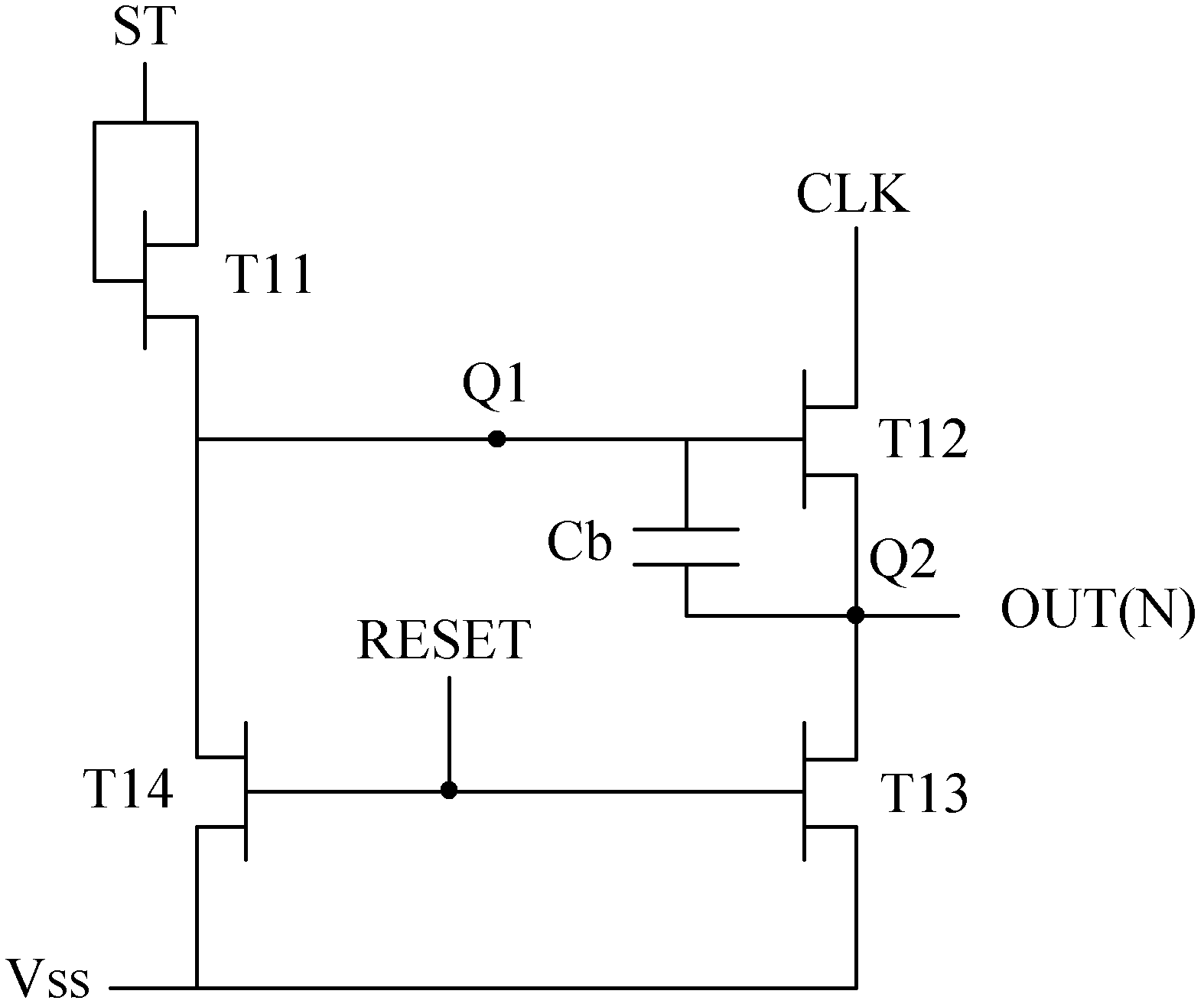
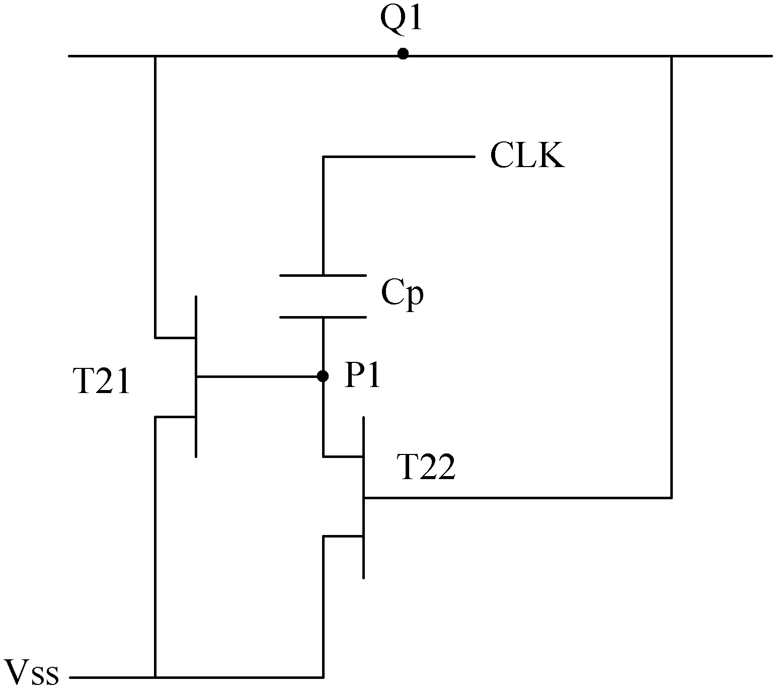
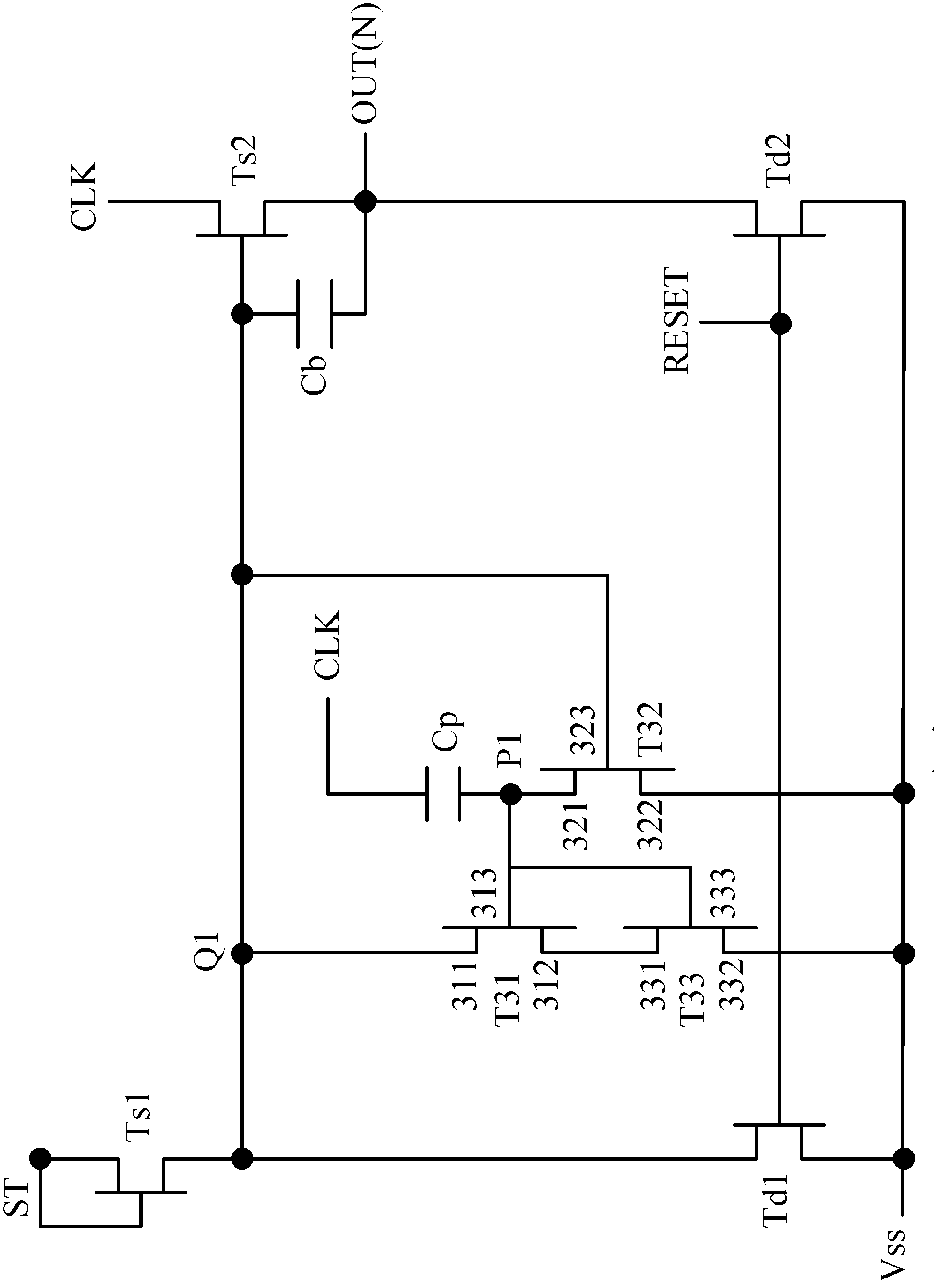
[0012] One object of the present invention is to provide a gate drive circuit of a display to solve the problem that the transistors in the gate drive circuit are prone to leakage current

Method used


Image

  • Gate driving circuit of display
  • Gate driving circuit of display
  • Gate driving circuit of display

Examples


Embodiment Construction

[0035] The following descriptions of the various embodiments refer to the accompanying drawings to illustrate specific embodiments in which the present invention can be practiced.

[0036] Certain terms are used in the description and claims of the present invention to refer to specific components. Those skilled in the art should understand that hardware manufacturers may use different terms to refer to the same component.

[0037] "Includes" mentioned throughout the specification and claims is an open term, so it should be interpreted as "including but not limited to". In addition, the term "coupled" here includes any direct and indirect electrical connection means. Therefore, if it is described in this specification that the first element is coupled to the second element, it means that the first element can be directly electrically connected to the second element. element, or indirectly electrically connected to the second element through other elements or connection means. ...


PUM


Abstract

The invention discloses a gate driving circuit of a display, wherein at least one transistor is connected in series between a transistor connected with a node providing a high potential and a reference voltage signal input end, so that voltage load between the source electrode and the drain electrode of the transistor connected with the node is shared by the at least one transistor, thereby reducing the situation of current leakage of the transistor, improving the stability of the driving voltage of the gate driving circuit, and further promoting the reliability of the gate driving circuit.

Description

【Technical field】 [0001] The invention relates to a gate drive circuit of a display, in particular to a gate drive circuit of a display which can effectively reduce the leakage current of a transistor. 【Background technique】 [0002] A liquid crystal display (LCD) uses an electric field to control liquid crystal molecules with dielectric anisotropy to change light penetration and display images accordingly. A liquid crystal display generally includes a display panel with pixels arranged in a matrix and a driving circuit for driving the display panel. [0003] The above-mentioned driving circuit is generally divided into a source driving circuit and a gate driving circuit. The source driving circuit converts the input data into a data signal, and the gate driving circuit generates a scanning signal for driving pixels to display the corresponding input data. image of the data. The source driving circuit and the gate driving circuit can operate according to the timing determi...

Claims


Application Information

Patent Timeline
Patent Type & Authority Applications(China)
IPC IPC(8): G09G3/36
CPCG09G3/36G09G3/3677G09G2300/0417G09G2310/0286G09G2320/0209G09G2330/021G09G2330/06G11C19/28G09G3/3648G09G2320/0214H03K17/162H03K17/6871
Inventor 陈世烽
Owner TCL CHINA STAR OPTOELECTRONICS TECH CO LTD
Learn More