
Gate driving circuit of display

一种闸极驱动电路、显示器的技术,应用在静态指示器、仪器、电子开关等方向,达到解决驱动电压稳定性、提升画面显示品质、提高可靠度的效果

Active Publication Date: 2013-11-06
TCL CHINA STAR OPTOELECTRONICS TECH CO LTD
View PDF2 Cites 1 Cited by
  • Summary
  • Abstract
  • Description
  • Claims
  • Application Information

AI Technical Summary

Problems solved by technology

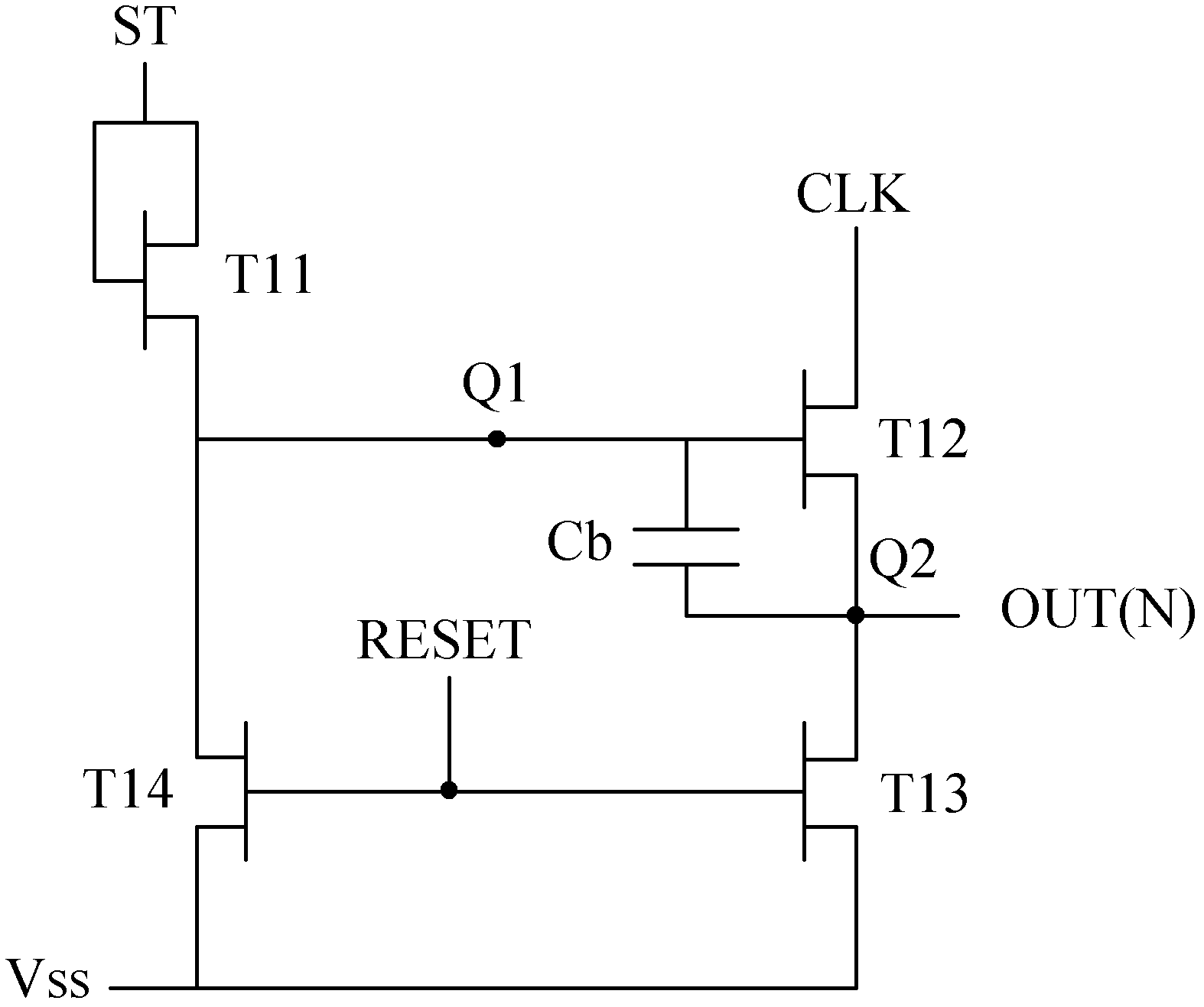
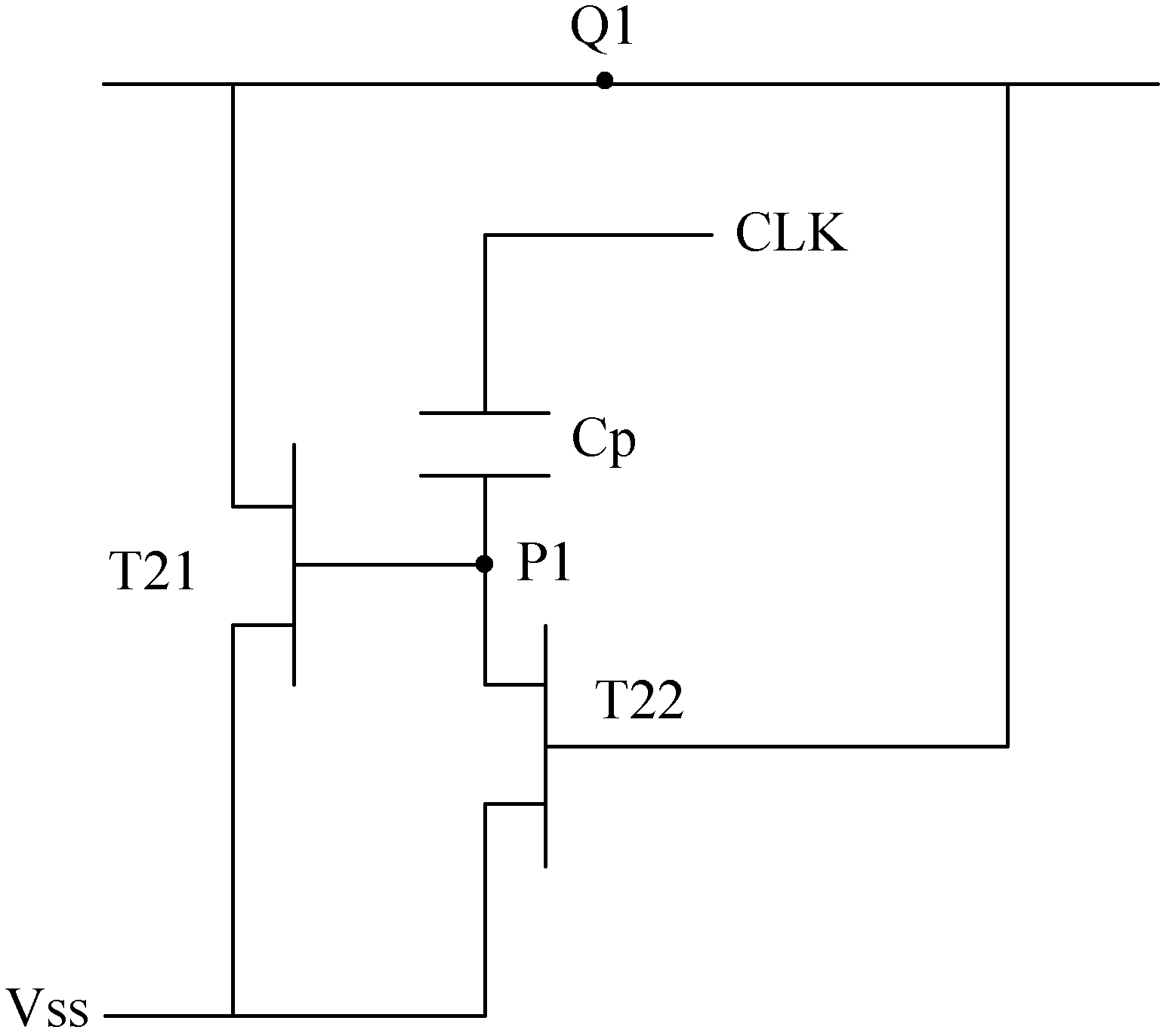
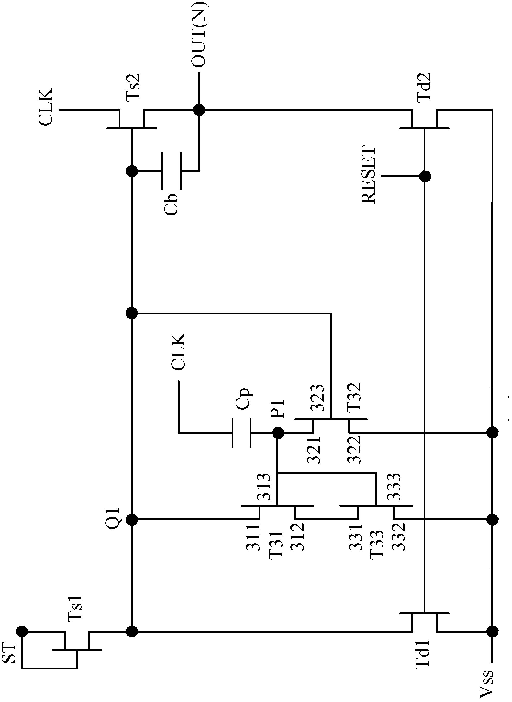
[0012] One object of the present invention is to provide a gate drive circuit of a display to solve the problem that the transistors in the gate drive circuit are prone to leakage current

Method used


Image

  • Gate driving circuit of display
  • Gate driving circuit of display
  • Gate driving circuit of display

Examples


Embodiment Construction

[0035] The description of the following embodiments refers to the attached drawings to illustrate specific embodiments that the present invention can be implemented.

[0036] In the specification and claims of the present invention, certain words are used to refer to specific elements. Those skilled in the art should understand that hardware manufacturers may use different terms to refer to the same element.

[0037] The "including" mentioned in the entire specification and claims is an open term, so it should be interpreted as "including but not limited to". In addition, the term "coupled" here includes any direct and indirect electrical connection means. Therefore, if the first element is described in this specification as being coupled to the second element, it means that the first element can be directly electrically connected to the second element. The element, or indirectly and electrically connected to the second element through other elements or connecting means. In additi...


PUM


Abstract

A gate electrode driving circuit of a display device. Utilized is at least one transistor (T33) serial-connected between a transistor (T31) connected to a node (Q1) providing a high potential and a reference voltage signal input end (Vss), while a voltage load between a source electrode and a drain electrode of the transistor (T31) connected to the node (Q1) is apportioned to the at least one transistor (T33). This reduces the occurrence of current leakage on the transistor (T31), thus increasing the stability of the driving voltage of the gate electrode driving circuit, thereby improving the reliability of the gate electrode driving circuit.

Description

【Technical Field】 [0001] The present invention relates to a gate drive circuit of a display, in particular to a display gate drive circuit which can effectively reduce the leakage current of a transistor. 【Background technique】 [0002] The liquid crystal display (LCD) uses an electric field to control the liquid crystal molecules with dielectric anisotropy to change the light transmittance and display images accordingly. A liquid crystal display usually includes a display panel with pixels arranged in a matrix and a driving circuit for driving the display panel. [0003] The above-mentioned driving circuit is generally divided into a source driving circuit and a gate driving circuit. The source driving circuit converts input data into a data signal, and the gate driving circuit generates a scan signal for driving the pixel to display the corresponding input The image of the data. The source drive circuit and the gate drive circuit can operate according to the timing determined b...

Claims


Application Information

Patent Timeline
Patent Type & Authority Patents(China)
IPC IPC(8): G09G3/36
CPCG09G3/36G09G3/3677G09G2300/0417G09G2310/0286G09G2320/0209G09G2330/021G09G2330/06G11C19/28G09G3/3648G09G2320/0214H03K17/162H03K17/6871
Inventor 陈世烽
Owner TCL CHINA STAR OPTOELECTRONICS TECH CO LTD
Learn More