

3D measuring device
A technology for three-dimensional measurement and measurement of objects, which is applied to measurement devices, optical devices, and image data processing. It can solve problems such as difficulty in detecting measurement objects, and achieve the effect of solving halo or shadow problems.
- Summary
- Abstract
- Description
- Claims
- Application Information
AI Technical Summary
Problems solved by technology
Method used
Image

Examples
no. 1 approach
[0061] The overall configuration of the three-dimensional measuring device 100 and the configuration of each unit
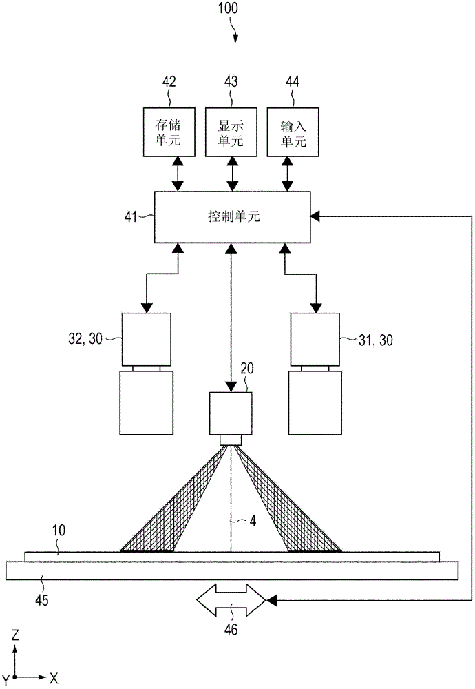
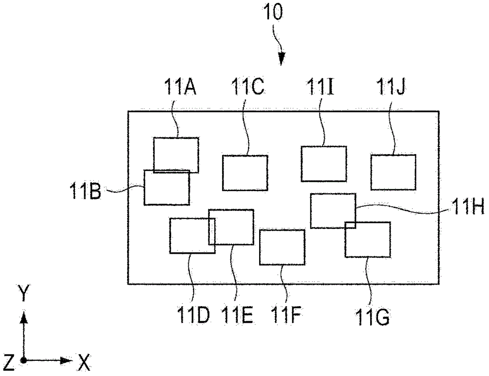
[0062] figure 1 is a diagram showing the three-dimensional measuring device 100 according to the first embodiment of the present invention. figure 2 is a diagram showing an example of a measurement object to be three-dimensionally measured by the three-dimensional measurement device 100 .
[0063] Such as figure 2 As shown, according to this embodiment, an example of a substrate 10 having a plurality of inspection regions 11 ( 11A to 11J ) will be described as an example of a measurement object to be three-dimensionally measured by the three-dimensional measurement apparatus 100 . For example, in the inspection area 11, solder is printed as the inspection object 12 (see Figure 7 and Figure 8 etc.). exist figure 2 In the example shown in , the substrate 10 has ten inspection zones 11 .
[0064] Such as figure 1 As shown, the three-dimensional measurin...
no. 2 approach
[0117] Next, a second embodiment of the present invention will be described. When describing the second embodiment, constituent elements having the same configurations and functions as those of the first embodiment described above will be assigned the same reference numerals, and descriptions thereof will not be repeated or simplified.
[0118] Figure 13 is a diagram showing a plurality of imaging areas 1 provided in a projectable area 2 according to the second embodiment. exist Figure 13 In the illustrated example, in the projectable area 2 , the first shot area 1C is set at a position of 0°, and the second shot area 1D is set at a position of 135°.
[0119] In the second embodiment, since the position of the second photographing area 1D is different from that of the first embodiment, the position of the photographing unit 30 (second photographing part 32) or the position of the opening 27 of the hood 26 is appropriately changed, To suit the location of the second shooti...
no. 3 approach
[0150] Next, a third embodiment of the present invention will be described. The third embodiment differs from the above-described embodiments in that the three-dimensional measuring apparatus 100 according to the third embodiment is switchable between a high-precision mode (first mode) and a high-speed mode (second mode).
[0151] The high-precision mode is a mode in which one inspection area 11 is imaged in a plurality of imaging areas by moving one inspection area 11 to positions of a plurality of imaging areas 1 . The high-speed mode is a mode for simultaneously imaging a plurality of imaging areas 1 by setting a plurality of inspection areas 11 in a plurality of imaging areas 1 at the same time.
[0152] Figure 20 is a diagram showing the arrangement of a plurality of shot areas 1 in a projectable area 2 according to the third embodiment. Such as Figure 20 As shown, in the third embodiment, five shooting areas 1E, 1F, 1G, 1H and 1I are set in the projectable area 2 . ...
PUM
 Abstract
Description
Claims
Application Information