Batch punching punch for perforator

A technology of punching machine and punch, applied in punching tools, metal processing, metal processing equipment, etc., can solve problems such as slow punching rate and inability to meet product requirements

Inactive Publication Date: 2015-06-10
苏州百诚精密科技有限公司
View PDF8 Cites 0 Cited by
  • Summary
  • Abstract
  • Description
  • Claims
  • Application Information

AI Technical Summary

Problems solved by technology

[0002] With the wide application of stamping technology, the requirements for stamping products in all walks of life are increasing, resulting in a wide variety of stamping product specifications. The traditional stamping industry process is: blanking - stamping - transfer - packaging, and Because the existing punching device only has double punches or single punches, the punching speed is slow, and because the size and spacing are relatively fixed, there are certain requirements for the size of the product, which cannot be applied to more product needs.

Method used


Image

  • Batch punching punch for perforator

Examples


Embodiment Construction

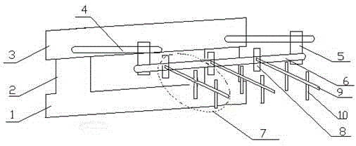
[0011] figure 1 The batch punching head of a punching machine shown includes a support 1, a guide post 2 is arranged above the support 1, a template 3 is provided above the guide post 2, and a fixed post 4 is provided on the template 3, The other end of the fixed column 4 is provided with a laterally moving slider 5, a lateral guide rail 6 is provided below the laterally movable slider 5, and a punch module 7 is arranged on the lateral guide rail 6, and the punch module 7 includes a punch A head fixing block 8, the punch fixing block 8 is provided with a punch guide rail 9, the punch guide rail 9 is provided with a punch 10, the punch module is not less than 1, and the punch module has 3.

[0012] After adopting the above structure, its characteristics are: move the template 3 up and down before punching to adjust the depth of the holes on the product, move the slider 5 back and forth and laterally to adjust the left and right distances of the holes on the material, and then ...


PUM


Abstract

The invention relates to a batch punching punch for a perforator, which comprises a rack, wherein a guide pillar is arranged above the rack; a template is arranged above the guide pillar; a fixed pillar is arranged on the template; the other end of the fixed pillar is provided with a horizontal moving sliding block; a horizontal guide rail is arranged below the horizontal moving sliding block; the horizontal guide rail is provided with punch modules; each punch module comprises a punch fixing block; each punch fixing block is provided with a punch guide rail; each punch guide rail is provided with a punch which is same in shape with but different in size from a product waste hole; the horizontal moving sliding block can move back and forth on the fixed pillar to horizontally adjust the punches; the punching position can be adjusted according to the punching requirement of the product; the punch fixing blocks can move left and right on the horizontal guide rail to adjust the space between the punch modules so as to further adjust the punching density; and the punches can move on the punch guide rail to finely adjust material holes so as to more accurately position the product hole. Therefore, the batch punching punch for a perforator is suitable for various products. Because the three punch modules are arranged, the punching speed is enhanced, and the production efficiency is improved.

Description

technical field [0001] The invention relates to a batch punching punch for a punching machine used in the stamping industry. Background technique [0002] With the wide application of stamping technology, the requirements for stamping products in all walks of life are increasing, resulting in a wide variety of stamping product specifications. The traditional stamping industry process is: blanking - stamping - transfer - packaging, and Because the existing punching device only has double punches or single punches, the punching speed is slow, and because the size and spacing are relatively fixed, there are certain requirements for the size of the product, which cannot be applied to more product requirements. Contents of the invention [0003] The technical problem to be solved by the present invention is to provide a batch punching punch for a punching machine that improves work efficiency, increases output and reduces cost. [0004] The technical solution adopted b...

Claims


Application Information

Patent Timeline
Patent Type & Authority Patents(China)
IPC IPC(8): B26F1/14B21D28/34
Inventor 董文军刘波波
Owner 苏州百诚精密科技有限公司
Why Eureka
Try Eureka