Multifunctional nursing chair bed

A multifunctional, bed and chair technology, applied in the field of patient care appliances, can solve the problems of easy access of the patient outside the basin, affecting the indoor environment, and large equipment investment, so as to improve indoor air quality, reduce labor intensity, and improve quality of life. Effect

Active Publication Date: 2012-08-22
康力元(天津)医疗科技有限公司
View PDF5 Cites 25 Cited by
  • Summary
  • Abstract
  • Description
  • Claims
  • Application Information

AI Technical Summary

Problems solved by technology

[0003] The purpose of the present invention is to solve the problem that the backrest adjustment angle of the existing hospital bed is small, the patient cannot achieve a sitting posture on the bed, and the patient can only be lifted or hoisted when the patient moves from the hospital bed to the wheelchair or from the wheelchair to the hospital bed.

Method used


Image

  • Multifunctional nursing chair bed
  • Multifunctional nursing chair bed
  • Multifunctional nursing chair bed

Examples


specific Embodiment approach 1

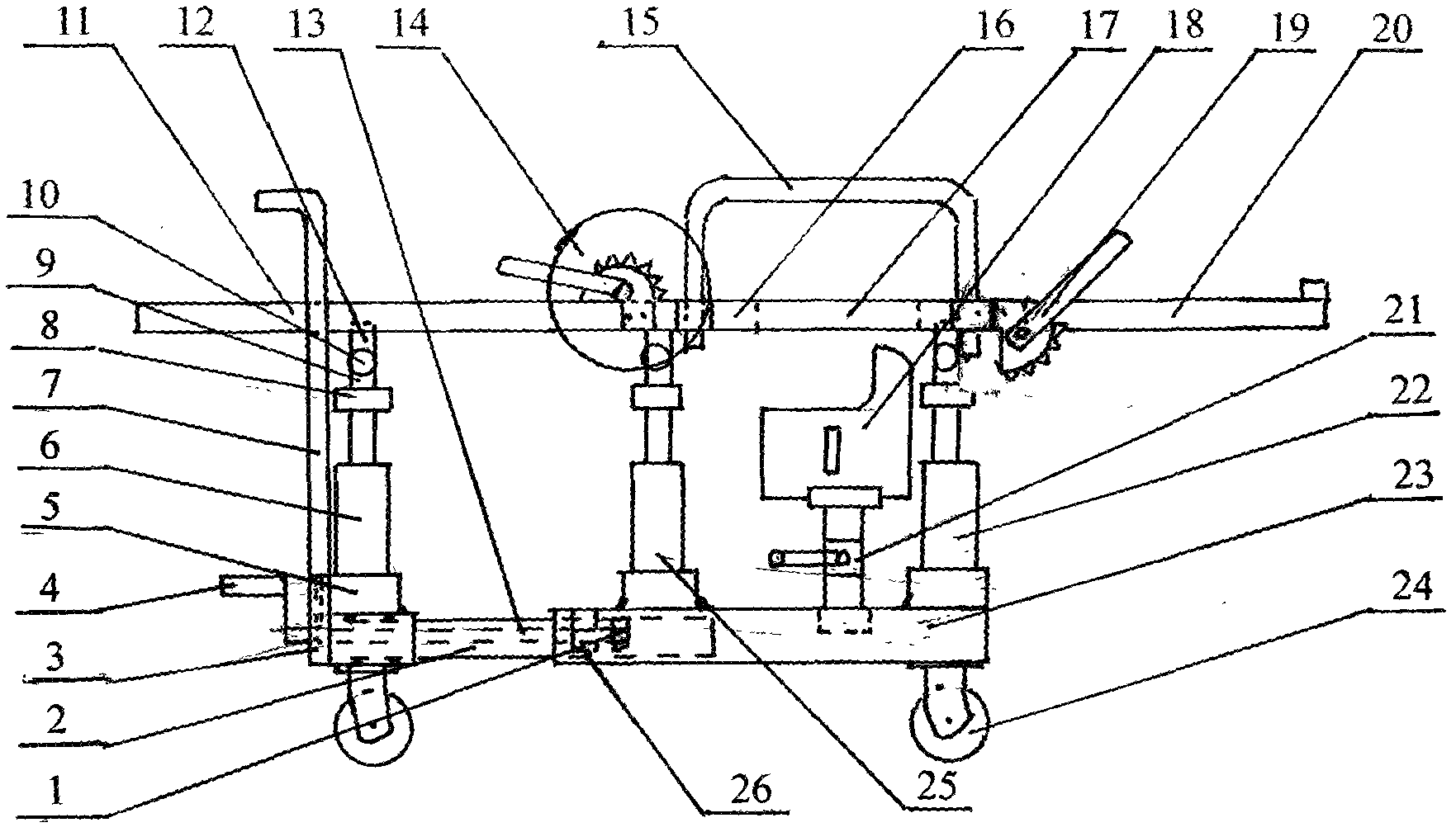
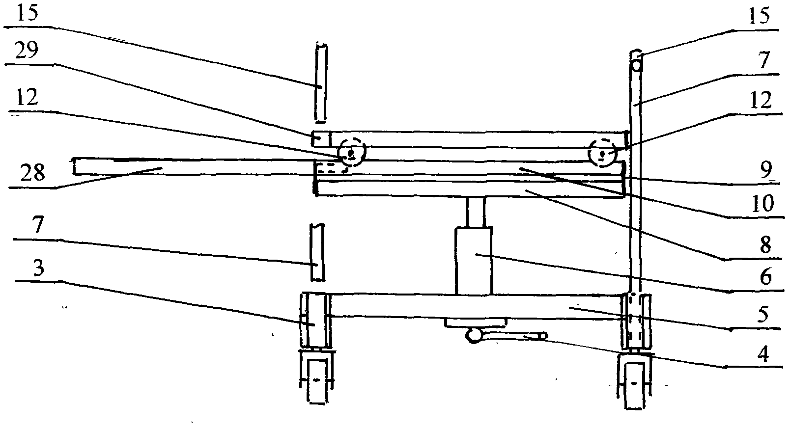
[0006] Specific implementation mode one: (see Figure 1 ~ Figure 4 ) This embodiment consists of a limit block 1, a pull pipe 2, a movable frame 5, a hydraulic cylinder 6, a tubular track 10, a backboard 11, a running wheel 12, a screw 13, a backrest angle regulator 14, a seat board 16, Knee bend angle regulator 19, calf plate 20, c hydraulic cylinder 22, fixed frame 23, b hydraulic cylinder 25; a hydraulic cylinder 6 is fixed on the movable frame 5, b hydraulic cylinder 25 and c hydraulic cylinder 22 are fixed on the fixed frame 23, the tops of a hydraulic cylinder 6, b hydraulic cylinder 25 and c hydraulic cylinder 22 are fixed below the middle part of the bracket 8, the upper ends of the bracket 8 are fixed with track brackets 9, and the top of the track bracket 9 is provided with a tubular track 10 , the two ends of the movable frame 5 are fixed with a drawing tube 2, the other end of the drawing tube 2 is arranged in the two ends of the fixed frame 23, the middle part of ...

specific Embodiment approach 2

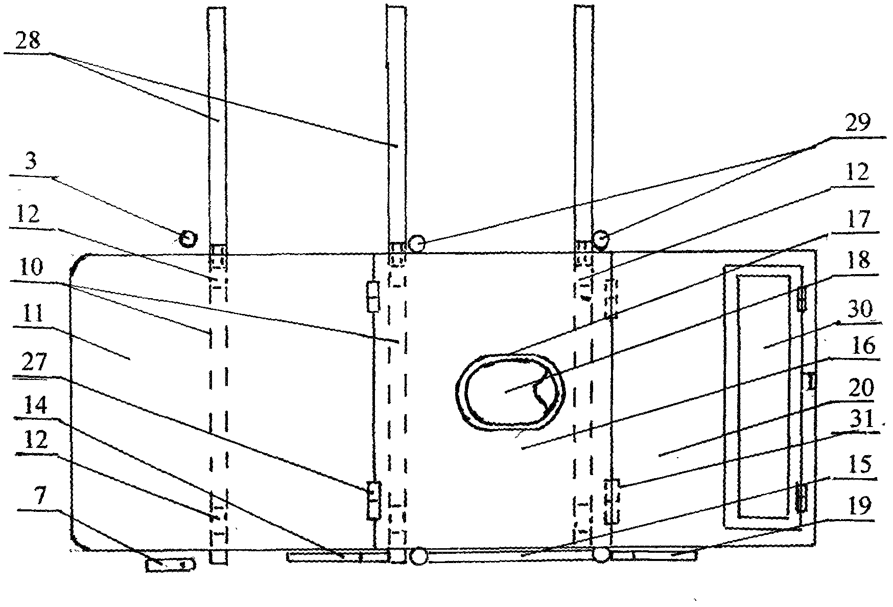
[0007] Specific implementation mode two: (see Figure 1 to Figure 5 ) The difference between this embodiment and the specific embodiment one is that a hydraulic cylinder 6, b hydraulic cylinder 25 and c hydraulic cylinder 22 are fixed on the lower frame 32, and two ends of the lower frame 32 are provided with two bed heads 35, two The root cross arm 33 is fixedly connected with the inner sides of the middle and upper parts of the two headboards 35, the cross arm 33 is provided with a cross arm guardrail jack 34, the guardrail 15 is inserted in the cross arm guardrail jack 34, and the base of the scissor lifter 21 is fixed. on the lower frame 32 . Other compositions and connection methods are the same as those in Embodiment 1.

specific Embodiment approach 3

[0008] Specific implementation mode three: (see Figure 1 to Figure 7 ) The difference between this embodiment and the second embodiment is that the c hydraulic cylinder 22 is fixed on the lower frame 32, a branch pipe 37 is fixed above the bracket 8, and horizontal support rods 36 are fixed on the inside of the two cross arms 33, and the backrest Plate 11 is fixed with backboard bushing 40, seat board 16 is fixed with seat board bushing 41, backrest board bushing 40 and seat board bushing 41 are provided with shaft 39, and the two ends of shaft 39 are covered with limit sleeve 38, The two ends of axle 39 are fixed on two cross arms 33. Other compositions and connection methods are the same as those in the second embodiment.


PUM


Abstract

A multifunctional nursing chair bed relates to a nursing device for patients in hospitals and families and aims to resolve problems that the adjusting angle of a backrest of an existing sickbed is small, a patient cannot sit on the sickbed, the patient needs to be lifted up or sling so as to move to a wheelchair from the sickbed or to the sickbed from the wheelchair, labor intensity is high when the patient is lifted up, equipment investment is high when the patient slings, most of toilet stools matched with the existing sickbed and the existing wheelchair are basin-shaped and are fixed, the patient is easy to defecate or urinate outside the toilet stools, and an indoor environment is affected. The multifunctional nursing chair bed has the advantages that the patient can be easily shiftedto the chair bed from a sickbed or to the sickbed from the chair bed, so that nursing labor intensity is relieved. The patient can sit at optional angles. The patient can sleep reversely and the likeby means of adjusting the heights of three hydraulic cylinders, and recovery of the patient is facilitated. A liftable toilet stool can improve a nursing environment and the quality of indoor air. Accordingly, the multifunctional nursing chair bed is suitable for hospitals, recuperation and hospice care institutions and families with patients.

Description

technical field [0001] The invention relates to a hospital and family patient care appliance, in particular to a multifunctional nursing bed and chair. Background technique [0002] Existing hospital beds have a small backrest adjustment angle, and patients cannot achieve a sitting posture on the hospital bed. Lifting the patient to move, the former is labor-intensive for nursing, while the latter requires a large investment in equipment; most of the toilets equipped with existing hospital beds and wheelchairs are basin-shaped and set in a fixed position, and the patient is easy to defecate outside the basin, which affects the indoor environment. environment. Contents of the invention [0003] The purpose of the present invention is to solve the problem that the backrest adjustment angle of the existing hospital bed is small, the patient cannot achieve a sitting posture on the bed, and the patient can only be lifted or hoisted when the patient moves from the hospital bed ...

Claims


Application Information

Patent Timeline
IPC IPC(8): A61G7/00A61G7/02A61G7/05A61G5/00A61G5/10
Inventor 宋大伟
Owner 康力元(天津)医疗科技有限公司
Why Eureka
Try Eureka