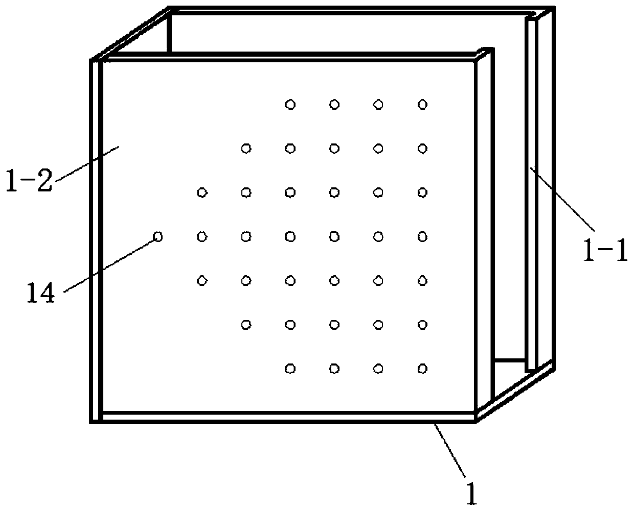
Multifunctional test device for soil mechanics plane strain problem and test method thereof
A plane strain and test device technology, which is applied to educational appliances, teaching models, instruments, etc., can solve the problems of unreasonable setting of vertical and lateral loading devices, waste of time, energy and money, and influence on simulation effects, etc., and achieves simple structure, Improve the applicability and improve the effect of the simulation effect
- Summary
- Abstract
- Description
- Claims
- Application Information
AI Technical Summary
Problems solved by technology
Method used
Image
Examples
Embodiment 1
[0077] Experimental demonstration of roadbed subsidence or uneven settlement using the above-mentioned device, such as Figure 10 As shown, follow the steps below:
[0078] S1, select or prepare the soil required for the test, determine the filling height of the foundation model 13, the filling width, height and slope gradient of the subgrade model 11.
[0079] S2, when simulating the subgrade collapse, fill the foundation model 13 required for the test in the model box 1, and embed the water bag 8 in the foundation model 13 near the side wall of the model box 1, and the top of the water bag 8 is level with the bottom surface of the roadbed model 11 Qi, the water bag 8 is connected to the pool 10 outside the model box 1 through a water pipe, and the water pipe is provided with a valve 9 . When simulating the uneven settlement of the roadbed, the water bag 8 is buried inside the foundation model 13, the size of the water bag 8 for simulating the uneven settlement of the roadbe...
Embodiment 2
[0082] Using the above-mentioned device to carry out the demonstration of the pull-out test of the bar, such as Figure 11 As shown, follow the steps below:
[0083] S1, select or prepare the soil required for the test, select the type, specification and quantity of the reinforcement 17, and determine the vertical spacing of the reinforcement 17;
[0084] S2, fill the foundation model 13 required for the test in the model box 1, and bury the reinforcement material 17 in layers according to the requirements in the foundation model 13. One end of the reinforcement material 17 reserves a certain free end on the outside of the model box 1, and the free end wears The slit of the stacked side plate 31 is connected to the horizontal drawing device; the vertical loading device is evenly loaded on the top of the foundation model 13 through the rigid foundation 18, and the bottom of the rigid foundation 18 is uniformly equipped with a plurality of thin-film pressure sensors 19, and the ...
Embodiment 3
[0087] Use the above device to demonstrate the working principle of foundation pit support, such as Figure 12 As shown, follow the steps below:
[0088] S1, select or prepare the soil required for the test, and determine the parameters such as the height of the model and the depth of the foundation pit;
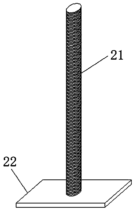
[0089] S2, fill the foundation model 13 required for the test in the model box 1, and use the winged slotted baffle 25 to simulate the support structure in the foundation pit. After the foundation model 13 is completed, the winged slotted baffle plate 25 is vertically buried in the soil to a certain depth, which is slightly greater than the design depth of the foundation pit, and then the foundation pit is excavated layer by layer from top to bottom and supported in time, and screwed The push rod 23 presses the winged slotted baffle 25 to prevent deformation of the foundation pit; a loading device is installed outside the top of the foundation pit, and the size of the rigid...
PUM
| Property | Measurement | Unit |
|---|---|---|
| Spacing | aaaaa | aaaaa |
Abstract
Description
Claims
Application Information
 - R&D
- Intellectual Property
- Life Sciences
- Materials
- Tech Scout
- Unparalleled Data Quality
- Higher Quality Content
- 60% Fewer Hallucinations
Browse by: Latest US Patents, China's latest patents, Technical Efficacy Thesaurus, Application Domain, Technology Topic, Popular Technical Reports.
© 2025 PatSnap. All rights reserved.Legal|Privacy policy|Modern Slavery Act Transparency Statement|Sitemap|About US| Contact US: help@patsnap.com


