Adjustable negative pressure continuous drainage system

A negative pressure and drainage tube technology, applied in wound drainage devices, suction devices, etc., can solve the problems of easy residual in the body, single surgical scope, siphoning and other problems

Active Publication Date: 2015-02-11
SHANDONG BAINUS MEDICAL INSTR
View PDF8 Cites 1 Cited by
  • Summary
  • Abstract
  • Description
  • Claims
  • Application Information

AI Technical Summary

Problems solved by technology

[0002] At present, after the operation, the patient will form congestion. In order to avoid wound inflammation, cross-infection, and accelerate wound healing, it is necessary to drain the wound. At present, the hospital uses low vacuum negative pressure drainage devices and high vacuum negative pressure drainage devices. The negative pressure drainage device is only suitable for thyroid and breast operations where the negative pressure value is not too high because the negative pressure value is about 10-15kpa. Due to the low negative pressure value, the congestion is not easy to drain, and it is easy to remain in the body. lead to infection, the negative pressure value of the high negative pressure drainage device is about 85-95 kpa, the negative pressure value is too high when it is first used, it is easy to cause siphon, and even cause damage to muscles, tissues and organs, so the scope of operation used is single and cannot It is used in abdominal cavity, thoracic cavity, bone marrow cavity, intracranial and nervous system and other operations, and when used, the drainage time is short and cannot continue to drain, while the negative pressure value required in conventional operations is about 40-60 kpa, while the above two kinds of negative pressure No pressure regulator can be realized, and the negative pressure can not be adjusted, which is extremely inconvenient to use

Method used


Image

  • Adjustable negative pressure continuous drainage system
  • Adjustable negative pressure continuous drainage system
  • Adjustable negative pressure continuous drainage system

Examples


Embodiment Construction

[0023] The present invention will be described in detail below in conjunction with the accompanying drawings.

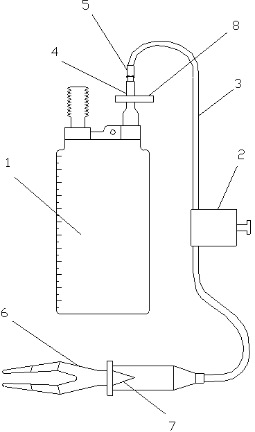
[0024] As shown in the figure, an adjustable negative pressure continuous drainage system includes a drainage bottle 1, a negative pressure regulator 2, a drainage tube 3 and a Y-shaped joint 6, wherein the drainage bottle 1 is provided with a liquid inlet 4 , the liquid inlet 4 is connected to the drainage tube 3 through a Luer connector 5, the liquid inlet 4 is provided with a sealing clip 8, the drainage tube 3 is provided with a negative pressure regulator 2, and the other end of the drainage tube 3 It is connected with the Y-shaped joint 6, and a one-way valve 7 is arranged in the connection of the Y-shaped joint 6.

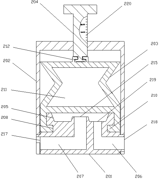
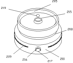
[0025] The negative pressure regulator 2 includes a base 201, a top cover 202, an adjustment screw 204 and a rubber adjustment pad 203. The top of the base 201 is provided with an annular terrace 205, and the base 201 is embedded with an "L"-shaped...


PUM


Abstract

The invention discloses an adjustable negative pressure continuous drainage system. The adjustable negative pressure continuous drainage system comprises a drainage bottle, a negative pressure regulator, a drainage pipe and a Y-shaped joint, and is characterized in that a liquid inlet is arranged on the drainage bottle, the liquid inlet is connected with the drainage pipe through a Luer joint, a sealing clamp is arranged on the liquid inlet, the negative pressure regulator is arranged on the drainage pipe, the other end of the drainage pipe is connected with the Y-shaped joint, and a one-way valve is connected in the Y-shaped joint. The adjustable negative pressure continuous drainage system disclosed by the invention is safe, smooth, thorough and continuous in drainage, can eliminate a dead space, realize the fit with an incision, form internal fixation and accelerate the healing of a wound, can perform sterile closed drainage and prevent postoperative infection, and can reduce the workload of doctors and nurses, realize convenience in use and adjustable negative pressure value and avoid non-smooth drainage or siphoning caused by too low or too high negative pressure value.

Description

technical field [0001] The invention belongs to the technical field of medical devices, in particular to an adjustable negative pressure continuous drainage system. Background technique [0002] At present, after the operation, the patient will form congestion. In order to avoid wound inflammation, cross-infection, and accelerate wound healing, it is necessary to drain the wound. At present, the hospital uses low vacuum negative pressure drainage devices and high vacuum negative pressure drainage devices. The negative pressure drainage device is only suitable for thyroid and breast operations where the negative pressure value is not too high because the negative pressure value is about 10-15kpa. Due to the low negative pressure value, the congestion is not easy to drain, and it is easy to remain in the body. lead to infection, the negative pressure value of the high negative pressure drainage device is about 85-95 kpa, the negative pressure value is too high when it is first...

Claims


Application Information

Patent Timeline
Patent Type & Authority Patents(China)
IPC IPC(8): A61M1/00A61M27/00
Inventor 丁伟
Owner SHANDONG BAINUS MEDICAL INSTR
Why Eureka
Try Eureka