

Zoom lens unit, imaging device and portable information terminal device
A zoom lens and unit system technology, applied in optical elements, instruments, optics, etc., can solve the problems of shortening the collapsed state of the zoom lens unit, insufficient zoom lens unit, and overall length reduction.
- Summary
- Abstract
- Description
- Claims
- Application Information
AI Technical Summary
Problems solved by technology
Method used
Image

Examples
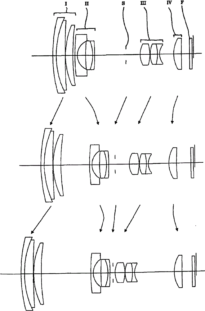
example 1
[0312] Table 1
[0313] f=5.07-34.50, F=3.48-5.65, ω=39.79-6.52
[0314]
[0315]
[0316] Aspheric surface (aspheric surface is the surface with an asterisk "*" in the above data. The situation is similar in the following example).
[0317] Sixth surface
[0318] K=0.0, A 4 =2.47187×10 -5 , A 6 =-2.33739×10 -6 , A 8 =1.40335×10 -7 ,
[0319] A 10 =-3.70011×10 -9 , A 12 =3.54383×10 -12 , A 14 = 6.39319×10 -13
[0320] Tenth surface
[0321] K=0.0, A 4 = -3.99709×10 -4 , A 6 = -3.19281×10 -6 , A 8 =-1.20904×10 -7 ,
[0322] A 10 =-3.19854×10 -8
[0323] Twelfth surface
[0324] K=0.0, A 4 =-8.15177×10 -4 , A 6 =1.43767×10 -5 , A 8 =-1.42505×10 -6 ,
[0325] A 10 =9.97953×10 -8
[0326] Thirteenth surface
[0327] K=0.0, A 4 =5.34757×10 -4 , A 6 =2.83041×10 -5 , A 8 =-2.34413×10 -6 ,
[0328] A 10 =1.69514×10 -7
[0329] Seventeenth surface
[0330] K=0.0, A 4 = -1.04517×10 -4 , A 6 =7.81280×10 -6 , A 8 = -2.51666×10 -7 ,
[0331] A 10 =4.09360×10 -9
[0332] Table 2
[0333] variable
[0334]
Short...
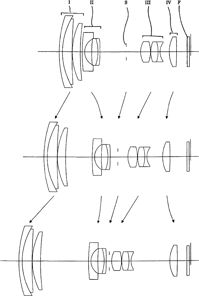
example 2
[0345] table 3
[0346] f=5.07-34.53, F=3.45-5.61, ω=39.75-6.55
[0347]
[0348]
[0349] Aspheric surface
[0350] Sixth surface
[0351] K=0.0, A 4 = 4.38118×10 -5 , A 6 =-3.28212×10 -6 , A 8 =1.67801×10 -7 ,
[0352] A 10 = -4.32537×10 -9 , A 12 =-1.26659×10 -11 , A 14 =1.27763×10 -12
[0353] Tenth surface
[0354] K=0.0, A 4 =-4.80018×10 -4 , A 6 = -4.53081×10 -6 , A 8 = -2.73503×10 -7 ,
[0355] A 10 = -5.07166×10 -8
[0356] Twelfth surface
[0357] K=0.0, A 4 =-8.76064×10 -4 , A 6 =1.71719×10 -5 , A 8 =-1.39333×10 -6 ,
[0358] A 10 =9.31505×10 -8
[0359] Thirteenth surface
[0360] K=0.0, A 4 =5.89357×10 -4 , A 6 =3.03606×10 -5 , A 8 =-2.25267×10 -6 ,
[0361] A 10 =1.54591×10 -7
[0362] Seventeenth surface
[0363] K=0.0, A 4 =-5.88625×10 -5 , A 6 =1.08911×10 -5 , A 8 = -4.32420×10 -7 ,
[0364] A 10 =7.34514×10 -9
[0365] Table 4
[0366] variable
[0367]
Short focal end
Intermediate focal length
Telephoto end
f=5.075
f=13.180
f=34.531
A
0.600
8.169
14.520
B
...
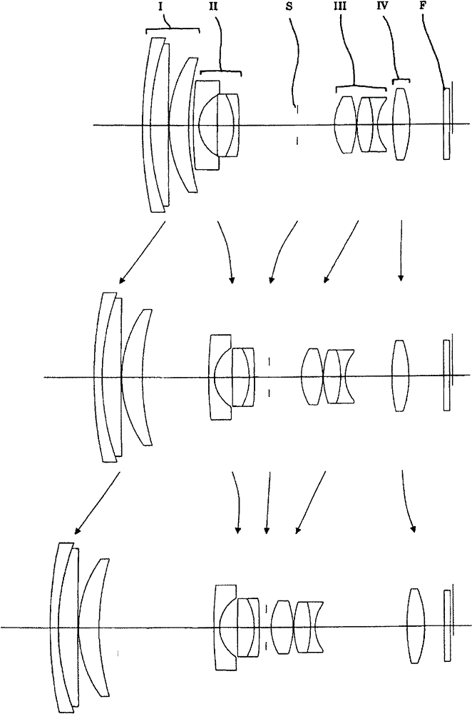
example 3
[0378] table 5
[0379] f=5.07-34.45, F=3.44-5.57, ω=39.77-6.81
[0380]
[0381] Aspheric surface
[0382] Fourth surface
[0383] K=0.0, A 4 = -2.61959×10 -6 , A 6 = -4.61000×10 -8 , A 8 =4.12097×10 -10 ,
[0384] A 10 = -2.83406×10 -12
[0385] Sixth surface
[0386] K=0.0, A 4 =4.69989×10 -5 , A 6 = -6.00298×10 -6 , A 8 =2.85972×10 -7 ,
[0387] A 10 = -4.67475×10 -9 , A 12 =-8.20307×10 -11 , A 14 =2.46554×10 -12
[0388] Tenth surface
[0389] K=0.0, A 4 = -5.17867×10 -4 , A 6 = -9.91338×10 -6 , A 8 = -2.02961×10 -7 ,
[0390] A 10 = -5.38642×10 -8
[0391] Twelfth surface
[0392] K=0.0, A 4 = -7.45563×10 -4 , A 6 =1.45957×10 -5 , A 8 = -1.41743×10 -6 ,
[0393] A 10 =1.11141×10 -7
[0394] Thirteenth surface
[0395] K=0.0, A 4 =7.01916×10 -4 , A 6 =2.59719×10 -5 , A 8 =-2.44987×10 -6 ,
[0396] A 10 =1.76570×10 -7
[0397] Seventeenth surface
[0398] K=0.0, A 4 =-2.49031×10 -5 , A 6 = 6.74925×10 -6 , A 8 =-2.86346×10 -7 , A 10 =4.04476×10 -9
[0399] Table 6
[0400] variable
[0401]
Short...
PUM
 Abstract
Description
Claims
Application Information