Image forming apparatus

An image and component technology, applied in the field of image forming devices, can solve problems such as wiring damage, failure to recognize state information, failure to control normally, etc.

Active Publication Date: 2015-04-22
KYOCERA DOCUMENT SOLUTIONS INC
View PDF8 Cites 0 Cited by
  • Summary
  • Abstract
  • Description
  • Claims
  • Application Information

AI Technical Summary

Problems solved by technology

If the wiring is caught repeatedly, the wiring will be damaged and the LED cannot be controlled normally.
As a result, the user cannot recognize the state information

Method used


Image

  • Image forming apparatus
  • Image forming apparatus
  • Image forming apparatus

Examples


Embodiment Construction

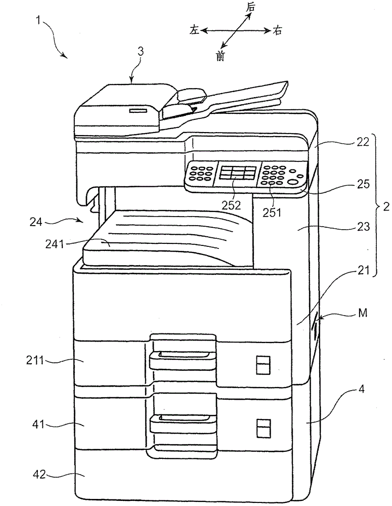
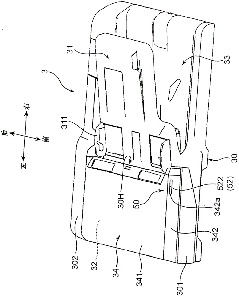
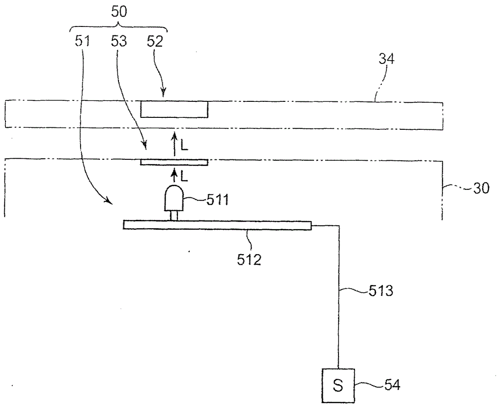
[0019] Embodiments of the present invention will be described in detail below based on the drawings. figure 1 is a perspective view showing the appearance of an image forming apparatus 1 according to an embodiment of the present invention, figure 2 is a perspective view showing the appearance of the automatic document feeder 3, image 3 It is a schematic diagram schematically showing the structure of the display device of the automatic document feeder. Here, although the image forming apparatus 1 is described as an internal discharge copier, the image forming apparatus of the present invention may be a printer, a facsimile machine, or a digital multifunction machine having these functions.

[0020] The image forming apparatus 1 includes: an apparatus main body 2 having a substantially rectangular parallelepiped-shaped box structure, and having an internal space (inner body paper discharge portion 24) and a main body casing 30; and an additional paper feeding unit 4 assembled...


PUM


Abstract

An image forming apparatus 1 is provided with an apparatus main body 2 for performing a predetermined process on a sheet, a cover 34 openable and closable relative to the apparatus main body 2, a light emitting unit 51 provided in the apparatus main body 2 and including an emission source 511 for generating light, a control board 512 for controlling the emission source 511 and causing it to generate the light and wiring 513 electrically connected to the control board 512, and a display member (52) provided in the cover 34, arranged to face the emission source 511 and including an incident portion 521 on which the light is incident, an output portion 522 for outputting the light to the outside and a light guide portion 523 for guiding the light from the incident portion 521 to the output portion 522.

Description

technical field [0001] The present invention relates to an image forming apparatus, and more particularly, to an image forming apparatus having a display device that displays status information of the image forming apparatus. Background technique [0002] Conventional image forming apparatuses generate various status information accompanying the image forming process of forming an image on a sheet. The status information includes, for example, information for notifying that the toner is insufficient, that a paper jam has occurred, and that the sheet is insufficient. LEDs (Light Emitting Diodes) are often used as display devices for notifying the user of such state information. [0003] A display device generally includes a light emitting unit and a display unit. The light emitting unit has an LED as a light source; a control board that controls the LED to emit light based on detection by a detection device that detects status information of the image forming device; and wi...

Claims


Application Information

Patent Timeline
Patent Type & Authority Patents(China)
IPC IPC(8): G03G15/043G03G15/00H04N1/00
CPCG03G15/60H04N1/00551H04N1/1017G03G21/1633G03G15/5016H04N1/00477H04N2201/0422H04N1/00493G03G15/00H04N1/00
Inventor 冈田武彦
Owner KYOCERA DOCUMENT SOLUTIONS INC
Why Eureka
Try Eureka