Traffic signal phase position configuration system

A traffic signal and configuration system technology, applied in the field of intelligent transportation, can solve the problems of difficult configuration phase, difficult for users to use, and heavy workload, so as to improve the traffic capacity of the intersection, reduce the waiting time at the intersection, and reduce the pollution of the ecological environment. Effect

Active Publication Date: 2012-08-29
SHANGHAI BAOSIGHT SOFTWARE CO LTD
View PDF4 Cites 22 Cited by
  • Summary
  • Abstract
  • Description
  • Claims
  • Application Information

AI Technical Summary

Problems solved by technology

The traditional phase configuration is realized by configuring the colors of the light groups corresponding to all phases (including the main phase and the transition phase). The traditional phase configuration is to directly configure each light group (up to 48 light groups). The color of the phase (including the main phase and the transition phase) needs to be changed one by one for each light group, the workload is very heavy, and the user is very inconvenient and unintuitive
This configuration method, the configuration process is very complicated, the interface display is not intuitive, and it is difficult for users to use
As a result, once the traffic signal control system project is completed, the user will not modify the signal characteristic parameters according to the actual road conditions due to the difficulty in configuring the phase, so that the powerful functions of the traffic signal control system cannot be well realized.

Method used


Image

  • Traffic signal phase position configuration system
  • Traffic signal phase position configuration system
  • Traffic signal phase position configuration system

Examples


Embodiment Construction

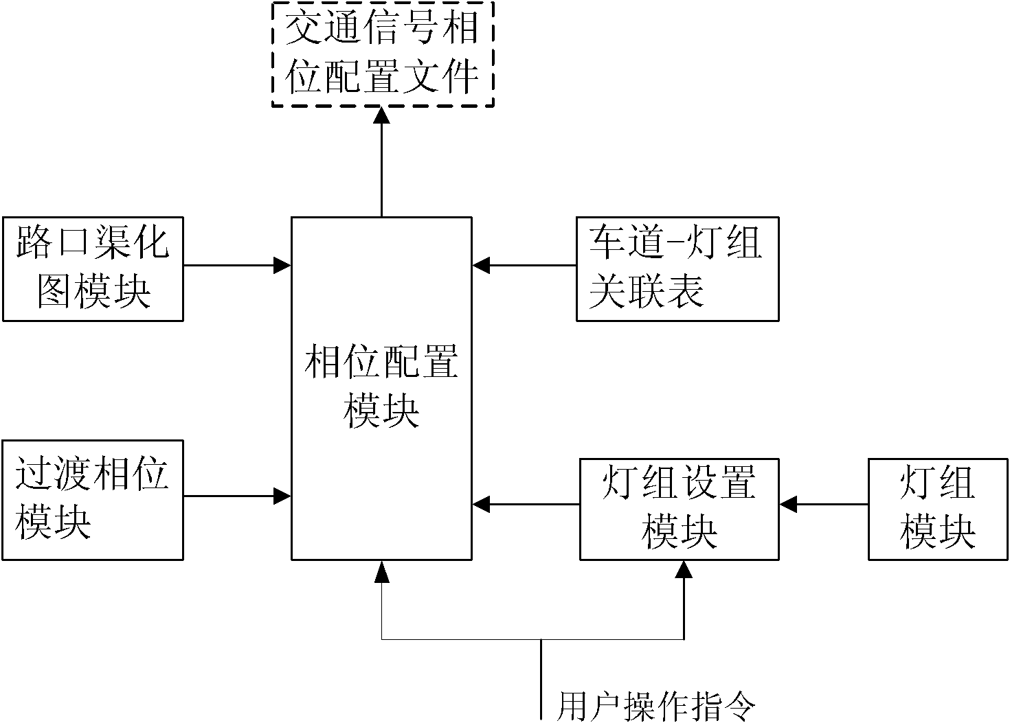
[0029] An embodiment of the traffic signal phase configuration system of the present invention is as follows: figure 1 As shown, including: including intersection channelization map module, light group module, lane-light group association table, light group setting module, transition phase module, phase configuration module;

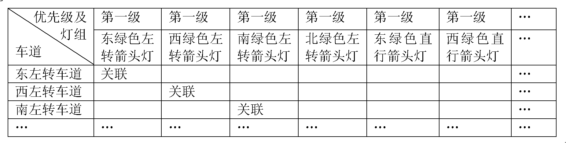
[0030] The intersection channelization map module is provided with one or more intersection channelization maps. Different intersection channelization maps have different channelization map identification codes. Each intersection channelization map includes a lane, and the lane has one or more ( Such as east left-turn lane, west left-turn lane, south left-turn lane, north left-turn lane, east through lane, west through lane, south through lane, north through lane, east right turn lane, west right turn lane, south straight left turn lane, north straight right-turn lane, east U-turn lane, west U-turn lane, south U-turn lane, north U-turn lane, etc.), diffe...


PUM


Abstract

The invention discloses a traffic signal phase position configuration system, which includes a road junction canalization image module, a lamp group module, a driveway-lamp group correlation chart, a lamp group setting module and a phase position configuration module, wherein the road junction canalization image module is provided with one or more types of road junction canalization images, and each road junction canalization image includes a driveway; the lamp group module is provided with a plurality types of lamp groups; the driveway-lamp group correlation chart includes a driveway identifying code, a lamp group type identifying code and a lamp group priority and correlation state; the lamp group setting module is used for receiving a lamp group selection command from a user and outputting a lamp group setting information of a road junction; and the phase position configuration module is used for receiving a traffic signal phase position configuration operating command from the user, so as to perform traffic signal phase position configuration of a road junction selected by the user and output lamp group states of main phases of sequence numbers at the road junction. The traffic signal phase position configuration system provided by the invention combines the traffic sign control and road junction canalization images, truly realizes the traffic signal phase position configuration through configuring driveway discharging state on the road junction canalization image, and is intuitional and convenient.

Description

technical field [0001] The invention relates to the technical field of intelligent transportation, in particular to a traffic signal phase configuration system. Background technique [0002] A very important system in the field of intelligent transportation is the traffic signal control system. In order to realize the intelligent control of traffic signals, it is necessary to configure the characteristic parameters of the traffic signals. In the process of configuring the characteristic parameters, the most important and most complicated configuration is the traffic signal. phase configuration. The traditional phase configuration is realized by configuring the colors of the light groups corresponding to all phases (including the main phase and the transition phase). The traditional phase configuration is to directly configure each light group (up to 48 light groups). The color of the phase (including the main phase and the transition phase) requires changing the color of ea...

Claims


Application Information

Patent Timeline
Patent Type & Authority Applications(China)
IPC IPC(8): G08G1/07
Inventor 刘其峰曾炜李东晓尹一瓴王夷盛兴东
Owner SHANGHAI BAOSIGHT SOFTWARE CO LTD
Why Eureka
Try Eureka