Connector apparatus

A technology of connectors and shells, applied in the field of connector devices, which can solve the problems of increasing the number of components, hindering the miniaturization of connector devices, and increasing manufacturing costs

Active Publication Date: 2012-08-29
DAIICHI SEIKO CO LTD
View PDF5 Cites 13 Cited by
  • Summary
  • Abstract
  • Description
  • Claims
  • Application Information

AI Technical Summary

Problems solved by technology

This increases the number of components and hinders the miniaturization of the e

Method used


Image

  • Connector apparatus
  • Connector apparatus
  • Connector apparatus

Examples


Embodiment

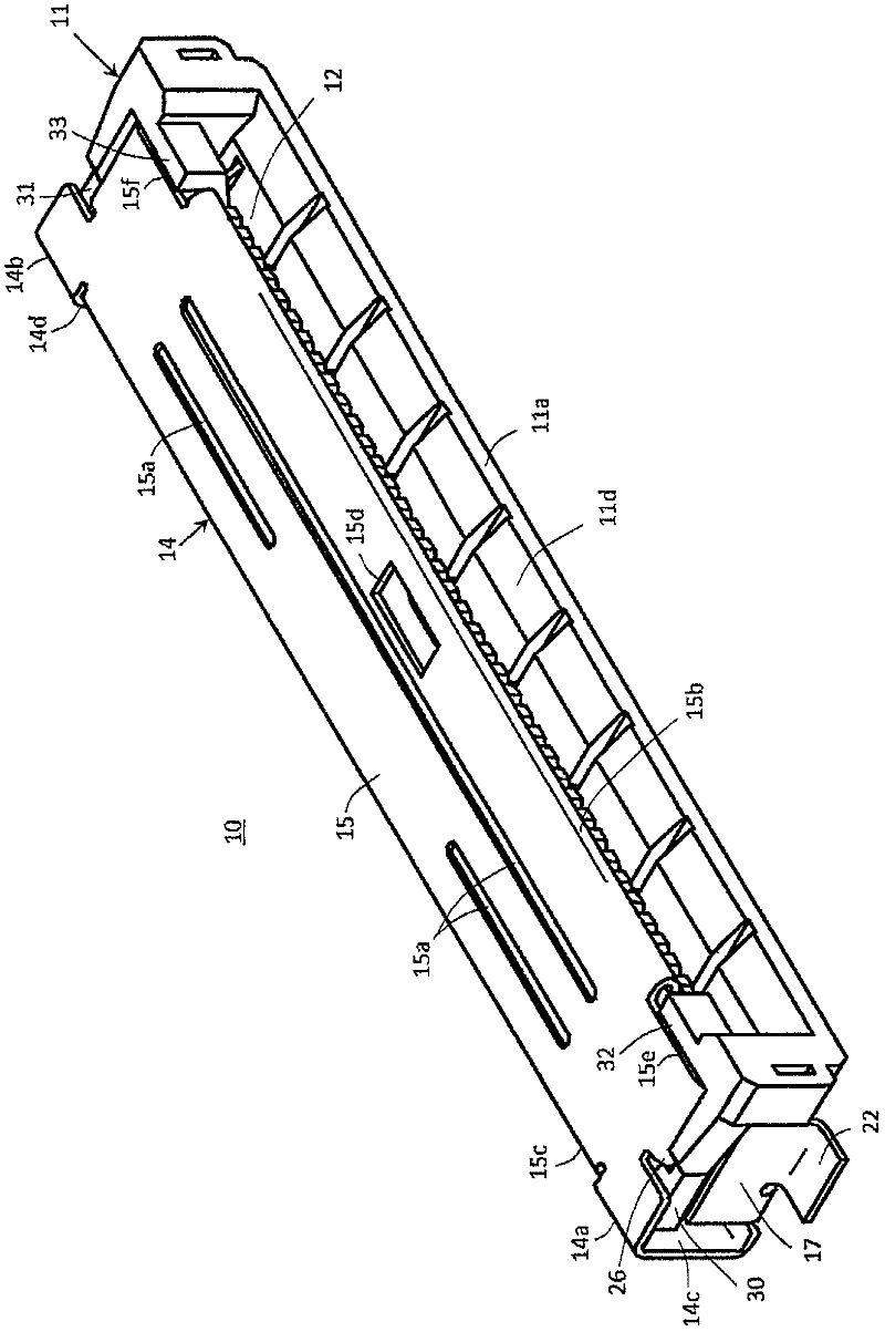
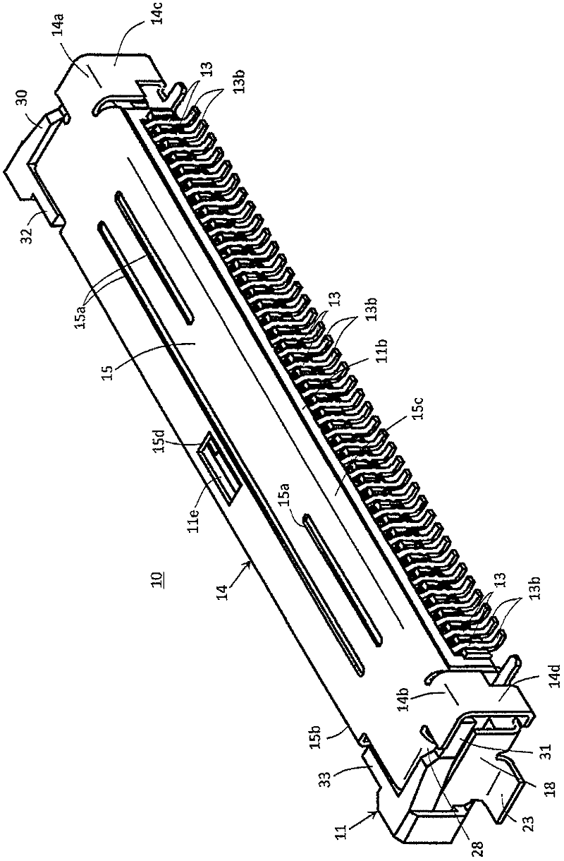
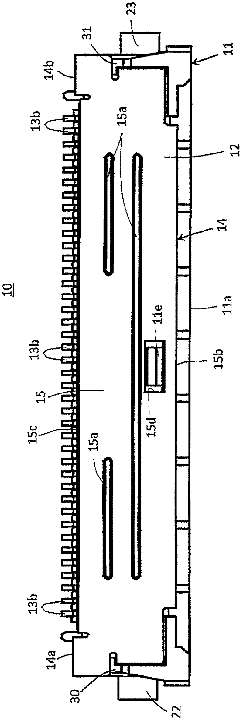
[0060] figure 1 (perspective view viewed from the front side), figure 2 (perspective view viewed from the rear side), image 3 (floor plan), Figure 4 (Front view) shows an example of a connector device according to the present invention.

[0061] exist Figure 1 ~ Figure 4 In the figure, the connector device 10 which is an example of the connector device concerning this invention is shown. Below, will image 3 The right side of the illustrated connector device 10 is designated as the front and the left side as the rear. thus, Figure 4 The front side of the connector device 10 is shown. below, toward Figure 4 The front side of the connector device 10 shown, the upper side, the lower side, the left side, and the right side are defined as "upper", "lower", "left" and "right", or as "upper" and "lower". ", "Left", "Right".

[0062] Figure 1 ~ Figure 4 The shown connector device 10 is equipped with a housing 11 formed of an insulating material such as synthetic resi...


PUM


Abstract

An electrical connector comprising a housing (11) provided with an opening (12) through which a flat circuit device (40) is inserted into the housing (11), a plurality of conductive contacts (13) arranged on the housing (11) for contacting with connecting terminals (41) on the flat circuit device (40) in the housing (11), and a shell member (14) mounted on the housing (11) and provided therein with a holding portion (26; 28) for holding the flat circuit device (40) in the housing (11) and a manipulatable releasing portion (15) for releasing the flat circuit device (40) from holding by the holding portion (26; 28), characterized in that the holding portion (26; 28) is constituted to extend from a portion (14a; 14b) of the shell member (14) provided for covering one of opposite plate-shaped portions (11a,11b) of the housing (11) into an inside of the housing (11) and to have an engaging projection (25; 27) formed thereon for engaging with and disengaging from the flat circuit device (40) selectively, and the manipulatable releasing portion (15) is constituted with the portion of the shell member (14) provided for covering the plate-shaped portion (11c) of the housing (11) for moving with the holding portion (26; 28) in a direction intersecting a contact-arrangement direction.

Description

technical field [0001] The invention described in the "Claims" of this application relates to a connector device for use in a connection terminal portion provided on a wiring board member such as a flexible printed circuit board (FPC) or a flexible flat cable (FFC). It is electrically connected with other wiring substrates such as solid wiring substrates, and includes the following components: snap unit, which is installed on a solid wiring substrate, etc., and is used as a component for inserting wiring plate-shaped components to prevent it from coming off Engaged with the inserted wiring board-shaped part; contact, the contact is connected to the connection terminal part in the inserted wiring board-shaped part. Background technique [0002] The relatively small flexible printed wiring boards, flexible flat cables and other wiring board-like components installed in various electronic equipment are electrically connected to the solid wiring boards on which various electrica...

Claims


Application Information

Patent Timeline
IPC IPC(8): H01R13/627H01R12/79
CPCH01R12/774H01R12/775H01R12/79H01R12/87H01R13/633H01R12/77H01R13/629
Inventor 岛田好伸尾关康介
Owner DAIICHI SEIKO CO LTD
Why Eureka
Try Eureka