LED (Light-Emitting Diode) dimming drive circuit

A dimming drive and circuit technology, applied in the direction of lamp circuit layout, light source, electric light source, etc., can solve the problem of continuous dimming and other problems

Inactive Publication Date: 2012-08-29
OCEANS KING LIGHTING SCI&TECH CO LTD +1
View PDF7 Cites 3 Cited by
  • Summary
  • Abstract
  • Description
  • Claims
  • Application Information

AI Technical Summary

Problems solved by technology

At present, in low-voltage places, DC-DC chopper circuits are basically used to drive LEDs, which have the advantages of low power consumption, high efficiency, stability and re

Method used


Image

  • LED (Light-Emitting Diode) dimming drive circuit
  • LED (Light-Emitting Diode) dimming drive circuit
  • LED (Light-Emitting Diode) dimming drive circuit

Examples


Embodiment Construction

[0012] The preferred embodiments of the present invention will be described in further detail below in conjunction with the accompanying drawings.

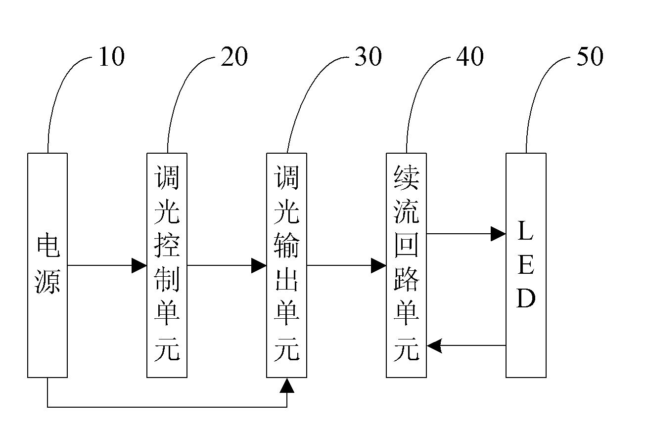
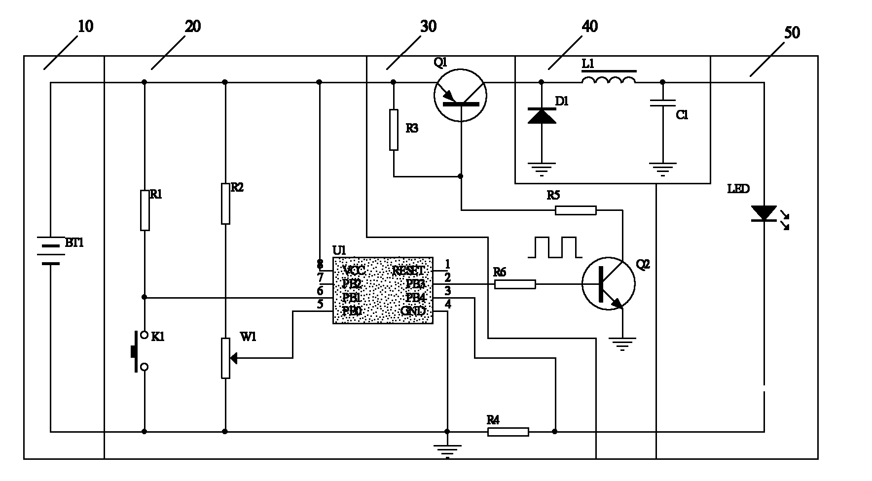
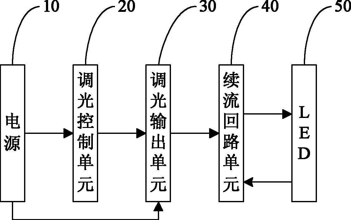
[0013] Such as figure 1 and 2 As shown, an LED dimming drive circuit includes a dimming control unit 20, a dimming output unit 30, and a freewheeling circuit unit 40; the dimming control unit 20 is electrically connected between the power supply 10 and the dimming output unit 30, and PWM pulses are output, and the PWM pulses pass through the dimming output unit 30 and control the brightness of the LED through the freewheeling circuit unit 40 to realize dimming of the LED 50; wherein, the dimming output unit 40 includes a first current limiting resistor R6, a driving transistor Q2 , the second current limiting resistor R5, the switching transistor Q1 and the third voltage dividing resistor R3; the base of the driving transistor Q2 is electrically connected to the dimming control unit through the first current limiting resistor R6;...


PUM


Abstract

The invention discloses an LED (Light-Emitting Diode) dimming drive circuit, comprising a dimming control unit, a dimming output unit and a subsequent-flow loop unit, wherein the dimming control unit is electrically connected between a power supply and the dimming output unit, and is used for outputting PWM (Pulse Width Modulation) pulse; and the PWM pulse passes through the dimming output unit and controls the brightness of an LED through the subsequent-flow loop unit so as to realize dimming of the LED. The LED dimming drive circuit provided by the invention has the advantages that an integrated dimming control chip is adopted, the A/D values of a PB0 pin and a PB4 pin are compared by utilizing the chip, the output pulse width of a PB3 pin is readjusted after comparison, and in such circulating mode, the dimming purpose is achieved.

Description

technical field [0001] The invention relates to an LED dimming driving circuit, in particular to an LED dimming driving circuit used in a portable lamp. Background technique [0002] As a new type of light source, LED has the characteristics of energy saving, environmental protection, and high efficiency. It is being widely used in various fields, and various LED drive circuits have also appeared. At present, in low-voltage places, DC-DC chopper circuits are basically used to drive LEDs, which have the advantages of low power consumption, high efficiency, stability and reliability, small size per unit power, and light weight; but DC-DC chopper circuits cannot Realizing the continuous dimming function of LED brings great inconvenience to users. Contents of the invention [0003] The purpose of the present invention is to provide an efficient and simple LED dimming drive circuit. [0004] Technical scheme of the present invention is as follows: [0005] An LED dimming dri...

Claims


Application Information

Patent Timeline
IPC IPC(8): H05B37/02
Inventor 周明杰黄柯青
Owner OCEANS KING LIGHTING SCI&TECH CO LTD
Why Eureka
Try Eureka