Adjustable photocontrol circuit of LED (light-emitting diode) lamp

A dimming control circuit and control circuit technology, which can be applied to the arrangement of electric lamp circuits, light sources, electric light sources, etc.

Active Publication Date: 2012-12-12
佛山市伊戈尔电子有限公司
View PDF2 Cites 0 Cited by
  • Summary
  • Abstract
  • Description
  • Claims
  • Application Information

AI Technical Summary

Problems solved by technology

The constant current source chip used in this circuit outputs a constant current instead of a pulse to the LED, which overcomes the defects of the first traditional dimming circuit and can achieve a good dimming effect, but because it has a two-stage circuit , which virtually reduces the efficiency of power supply, which is inconsistent with the current direction of energy saving

Method used


Image

  • Adjustable photocontrol circuit of LED (light-emitting diode) lamp
  • Adjustable photocontrol circuit of LED (light-emitting diode) lamp
  • Adjustable photocontrol circuit of LED (light-emitting diode) lamp

Examples


Embodiment Construction

[0018] The specific implementation manner of applying the solution of the present invention will be described below in conjunction with the accompanying drawings.

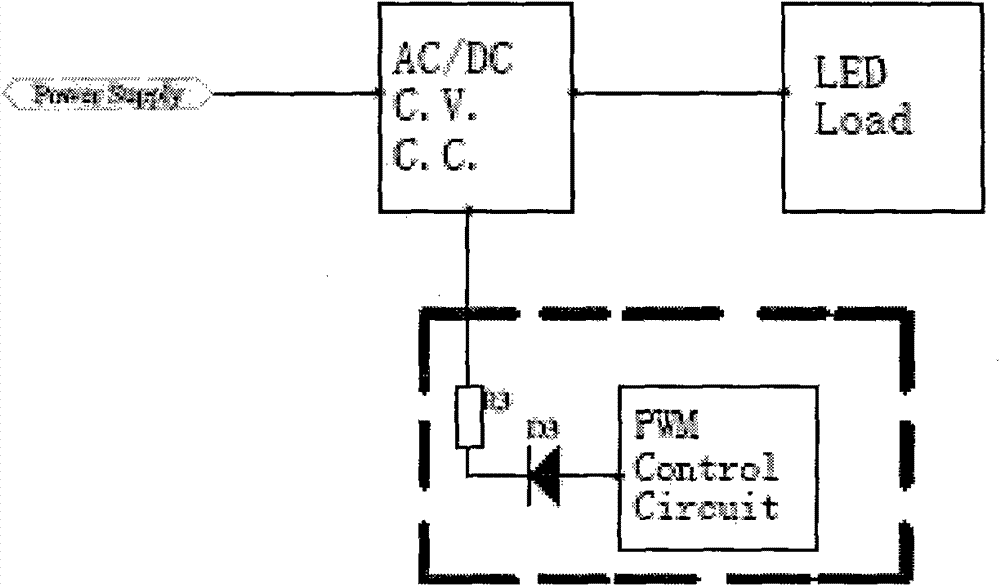
[0019] Such as figure 2 As shown, the power conversion circuit 1 is directly connected to the load LED lamp after completing the conversion of the mains voltage into a safe voltage, filtering and constant current and constant voltage circuit processing. In this way, the power conversion circuit 1 is no longer provided with a dedicated constant current IC chip, but is replaced by an ordinary constant current and constant voltage circuit. Connect the output terminal of the PWM control circuit at the feedback base point of the LED control circuit, and directly adjust the duty cycle of the signal by adjusting the output pulse width of the PWM control circuit, thereby realizing the current control of the load LED lamp, and then adjusting the LED The brightness of the lamp.

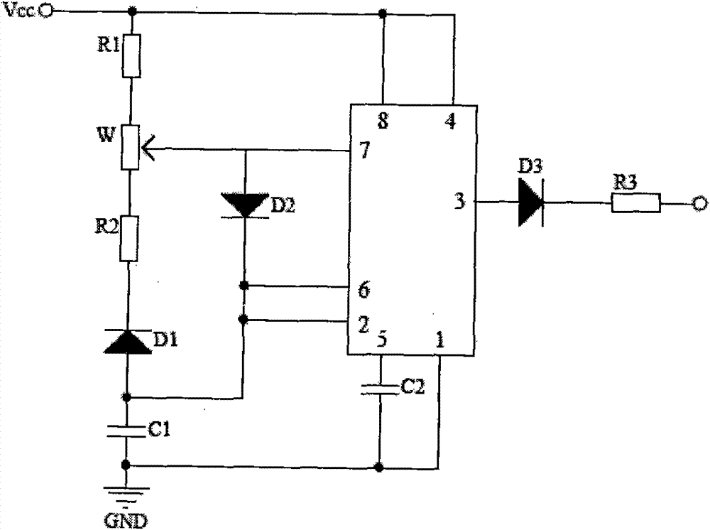
[0020] Such as image 3 Shown is a schema...


PUM


Abstract

The invention discloses an adjustable photocontrol circuit of an LED (light-emitting diode) lamp, which comprises a power supply conversion circuit capable of connecting an LED lamp load and a PWM (pulse width modulation) control circuit and is characterized in that the power supply conversion circuit comprises a voltage transformation circuit, a rectification filter circuit and an LED load control circuit, the output end of the PWM control circuit is sequentially connected with a diode D3 and a resister R3 in series, and the output end of the resister R3 is connected with a reference controlpoint (A) of the LED load control circuit. The standard control point (A) is an anodic control end of an opticalcoupler, a control end of a reference voltage source or a control end of a comparator. The PWM control circuit is powered by an auxiliary power supply or connected with the output end of the power supply conversion circuit. Because of the advantages, The invention can be applied to a similar laden control circuit of the LED lamp and the like.

Description

technical field [0001] The invention relates to the technical field of lighting control of LED lamps, in particular to the design of a dimmable control circuit for LED lamps. Background technique [0002] Ordinary dimmable LED circuits have the following two forms: [0003] The first solution, as disclosed in Chinese Patent No. 200620047055.9, titled "Pulse Width Energy-Saving LED Dimmable Table Lamp", adopts the adjustable pulse width adjustment generated by a timer integrated circuit such as NE555, and is equipped with a switch at the input end. Phase dimmer for dimming; this circuit uses pulse current to realize dimming function. Although the pulse frequency is so high that it cannot be detected by human eyes, it is harmful to the service life and working stability of the light-emitting diode, and at the same time, it is harmful to the power grid. There is some pollution. [0004] The second scheme, such as Chinese patent No. 200820085623.3, is named "dimmable LED light...

Claims


Application Information

Patent Timeline
Patent Type & Authority Patents(China)
IPC IPC(8): H05B37/02
Inventor 肖俊承熊川高
Owner 佛山市伊戈尔电子有限公司
Why Eureka
Try Eureka