Dimming circuit and light emitting device

A technology of dimming circuits and light-emitting modules, which is applied to electrical components and other directions, can solve problems such as fine adjustment of brightness, and achieve the effects of low cost, good dimming performance and simple structure.

Pending Publication Date: 2022-01-28
SHENZHEN HUOLE TECH DEV CO LTD
View PDF0 Cites 0 Cited by
  • Summary
  • Abstract
  • Description
  • Claims
  • Application Information

AI Technical Summary

Problems solved by technology

[0004] This application aims at the problem that the existing dimming circuit cannot finely adjust the brightness when the brightness requirement of the light-emitting module is low, and provides a dimming circuit and a light-emitting device. The dimming circuit is located between the input terminal and the light-emitting module. The switch module is set so that the switch module can adjust the duty ratio of the current input by the power supply module based on the modulation signal, so that the adjustment of the current of the light-emitting module is no longer limited to the starting point of the driving chip, and then the light-emitting module can be realized at low brightness. Fine Dimming on Demand

Method used


Image

  • Dimming circuit and light emitting device
  • Dimming circuit and light emitting device
  • Dimming circuit and light emitting device

Examples


Embodiment Construction

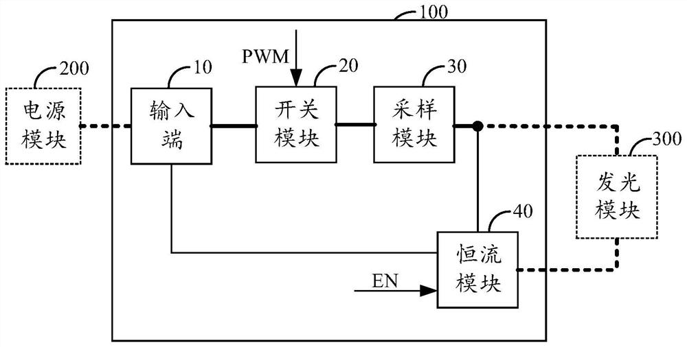
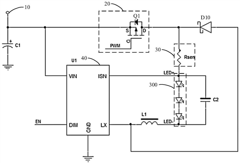
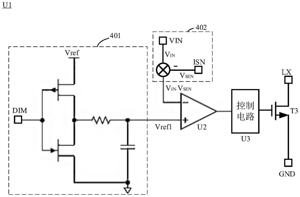
[0048] The following will clearly and completely describe the technical solutions in the embodiments of the present application with reference to the accompanying drawings in the embodiments of the present application. Wherein, the accompanying drawings are used for illustrative purposes only, represent only schematic diagrams, and should not be construed as limitations on the present application. Apparently, the described implementations are only some, not all, embodiments of the present application. Based on the implementation manners in this application, all other implementation manners obtained by persons of ordinary skill in the art without making creative efforts belong to the scope of protection of this application.

[0049] Unless defined otherwise, all technical and scientific terms used in this application have the same meaning as commonly understood by one of ordinary skill in the art. The terminology used in the description of the present application is only for t...


PUM


Abstract

The invention provides a dimming circuit and a light emitting device. The dimming circuit comprises an input end, a switch module and a constant current module. The input end is used for being electrically connected with a power module. The first connecting end of the switch module is electrically connected with the input end, the second connecting end of the switch module is used for being electrically connected with the light emitting module, and the switch module is used for receiving the modulation signal and repeatedly connecting or disconnecting the electric connection between the input end and the light emitting module according to the modulation signal, so that the duty ratio of the current input to the light emitting module by the power supply module is adjusted. The constant current module is connected in series in a loop where the light emitting module is located, and is used for adjusting the amplitude of the current input to the light emitting module by the power supply module. The duty ratio of the current input to the light emitting module by the power supply module is adjusted through the switch module, so that the purpose of dimming is achieved, and fine dimming of the light emitting module under the requirement of low brightness can be realized.

Description

technical field [0001] The present application relates to the technical field of light emitting devices, in particular to a dimming circuit and a light emitting device. Background technique [0002] In the field of lighting, LED, as an energy-saving and environmentally friendly light source product with long life and small size, is gradually replacing traditional light sources such as incandescent lamps and fluorescent lamps. High-power LEDs generally use constant current power supplies for power supply. [0003] At present, the dimming circuit on the market usually uses a constant current driver chip to dim the LED, and the current amplitude is changed by adjusting the amplitude of the analog voltage signal input to the driver chip or the duty cycle of the PWM modulation signal, so as to realize the adjustment of the brightness of the LED. adjust. However, in order to ensure that the driver chip can work stably, a reliable starting point needs to be set inside the driver c...

Claims


Application Information

Patent Timeline
Patent Type & Authority Applications(China)
IPC IPC(8): H05B45/30H05B45/345H05B45/325
CPCH05B45/30H05B45/345H05B45/325
Inventor 钟颖李波张聪胡震宇
Owner SHENZHEN HUOLE TECH DEV CO LTD
Why Eureka
Try Eureka